Flannel mode architecture
In Flannel mode, each ECS instance has only one primary network interface and no secondary network interfaces. The ECS instance and the pods on the node use the primary network interface to communicate with external networks.
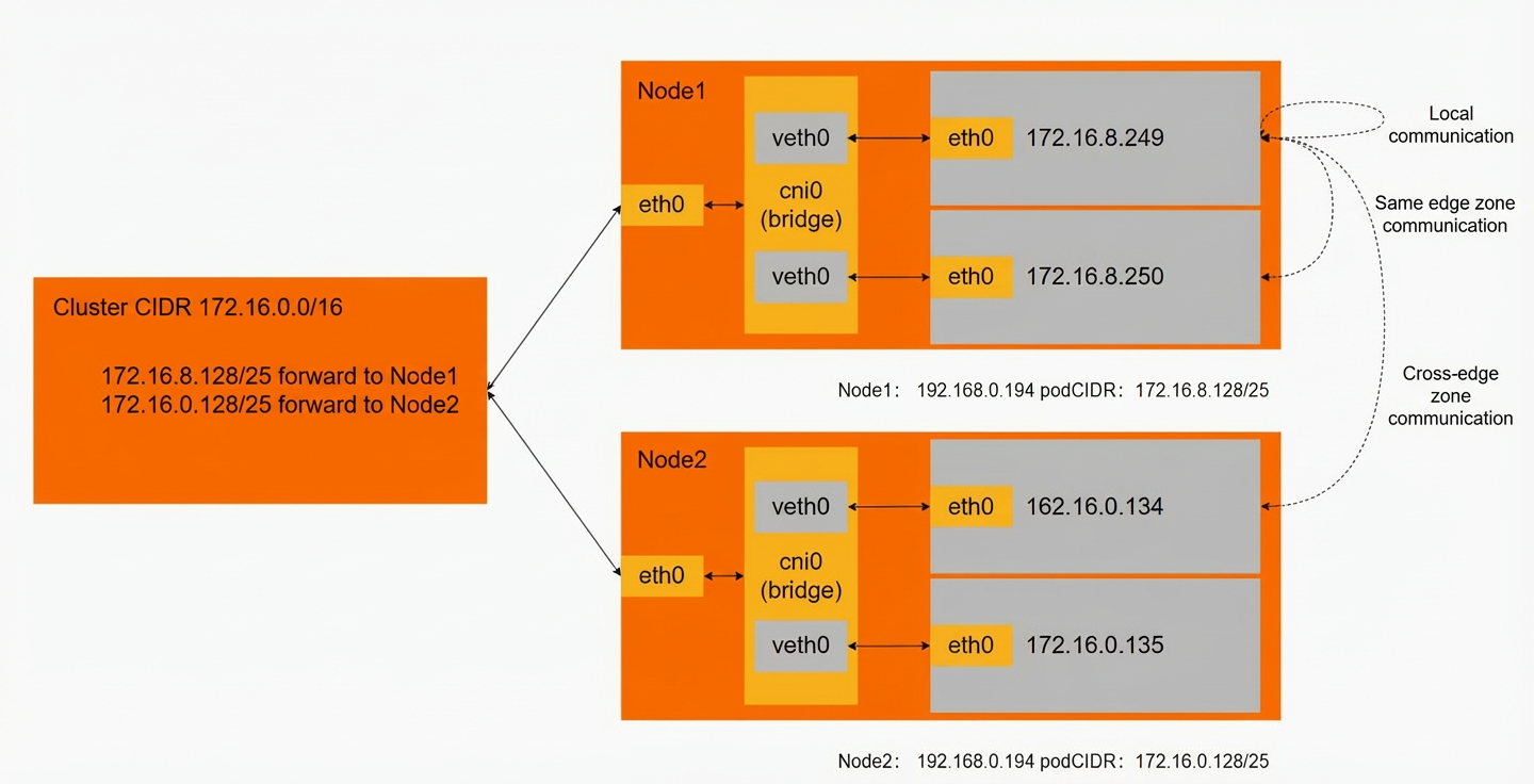
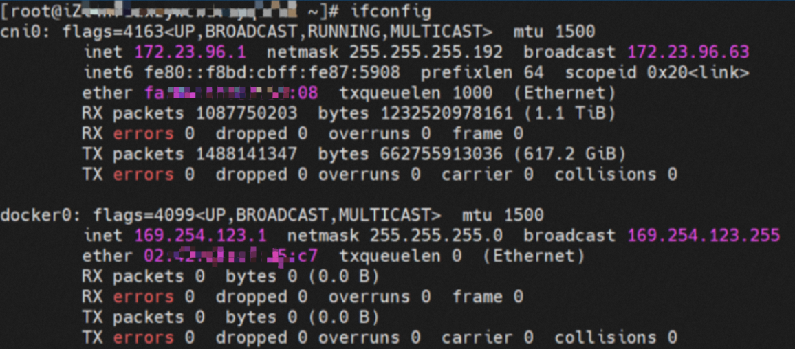
ACK Flannel creates a cni0 network interface on each node. This interface acts as a bridge between the pod network and the primary network interface (eth0) of the ECS instance.
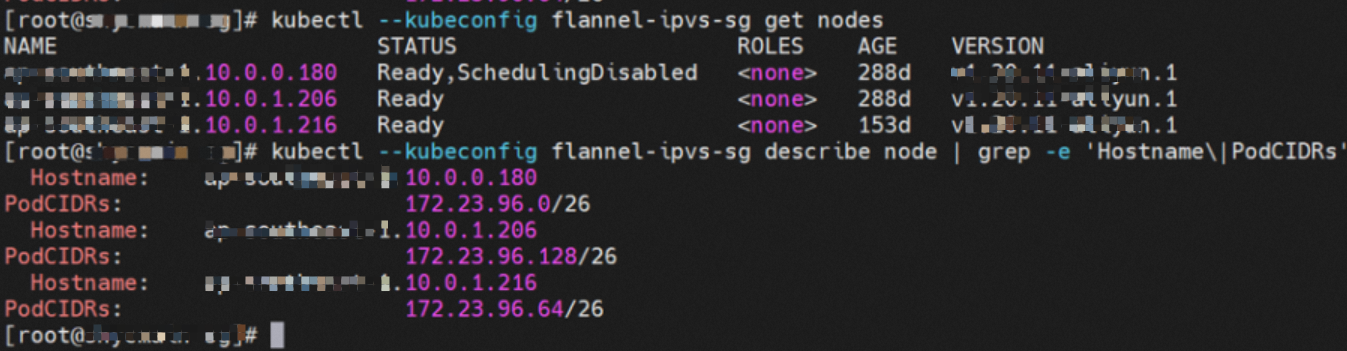
A Flannel agent starts on each node in the cluster. Each node is allocated a pod CIDR block, which is a subset of the ACK cluster's pod CIDR block.
The container's network namespace has an eth0 network interface and a route with the next hop pointing to this interface. The eth0 interface serves as the entry and exit point for data exchange between the container and the host kernel. The data link between the container and the host is established using a veth pair.
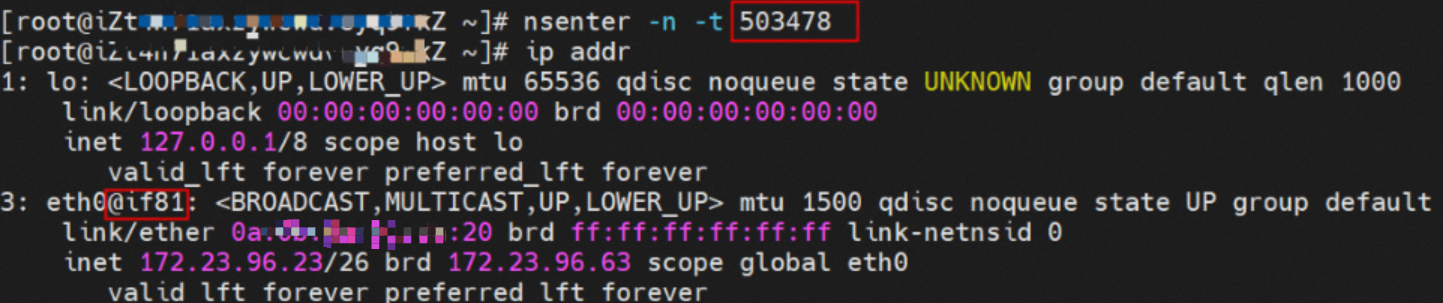
In the container's network namespace, running the ip addr command returns an `eth0@ifxxx` flag. The `xxx` corresponds to the veth pair in the network namespace of the ECS instance's operating system (OS).
In the ECS OS, you can run ip addr | grep xx: to find the `vethdxxx` network interface. This is the corresponding end of the veth pair on the ECS OS side.

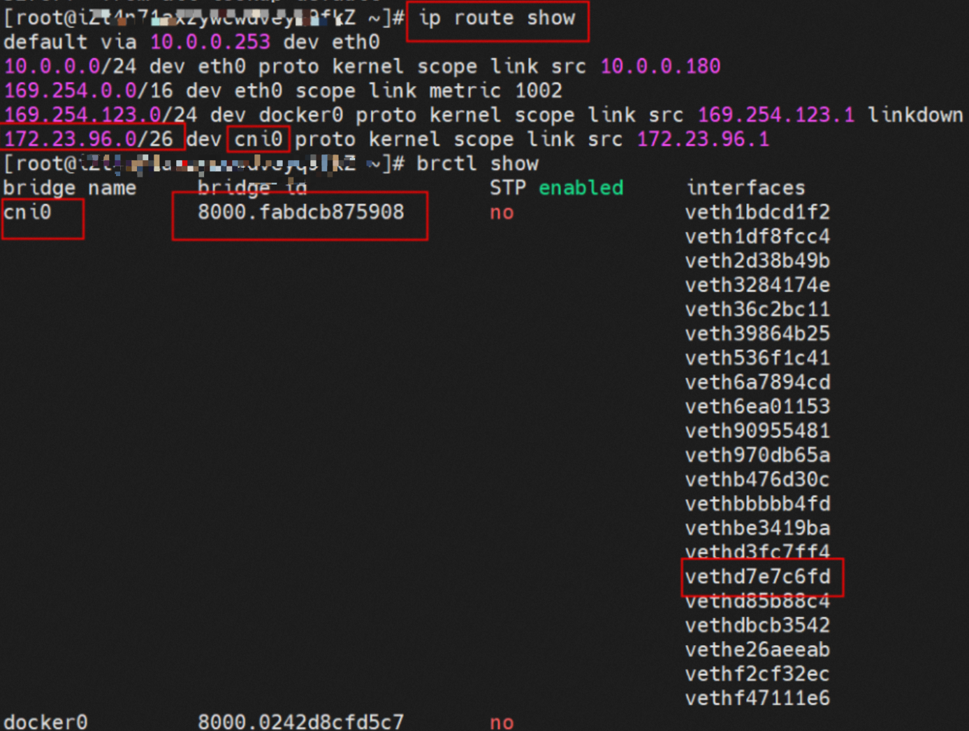
The data link between the container and the OS is now connected. According to the Linux routing table in the OS, all traffic destined for the pod CIDR block is forwarded to the cni0 network interface. The cni0 interface then uses a bridge to direct data streams to different `vethxxx` interfaces based on their destination. At this point, the complete ingress and egress link configuration between the ECS OS and the pod's network namespace is established.
Analysis of Flannel mode network data links
Based on the characteristics of container networks, the network links in Flannel mode can be divided into two main scenarios: services exposed by a pod IP address and services exposed by a Service. These can be further broken down into 10 specific sub-scenarios.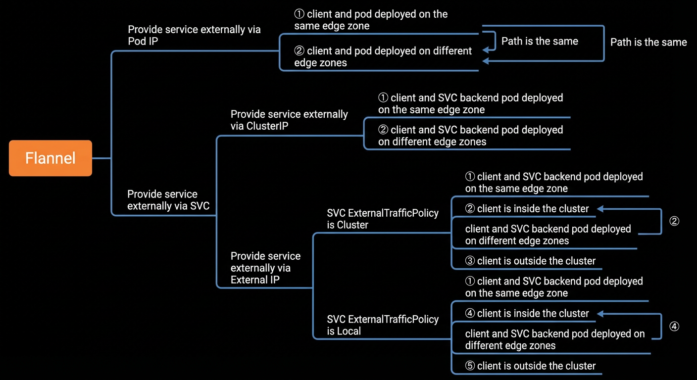
After analyzing and merging the data links of these 10 scenarios, they can be grouped into the following five typical scenarios:
The client and the server-side pod are deployed on the same ECS instance.
The client and the server-side pod are deployed on different ECS instances.
A client outside the cluster accesses a Service's external IP address when ExternalTrafficPolicy is set to Cluster.
A client inside the cluster accesses a Service's external IP address when ExternalTrafficPolicy is set to Local, and the server-side pod is on a different ECS instance.
A client outside the cluster accesses a Service's external IP address when ExternalTrafficPolicy is set to Local, and the server-side pod is on a different ECS instance.
Scenario one: The client and server-side pod are on the same ECS instance
This scenario includes the following sub-scenarios, which share the same data link:
A service is exposed by a pod IP address, and the client and pod are on the same node.
A service is exposed by a Service's cluster IP address, and the client and the Service's backend pod are on the same node.
A service is exposed by a Service's external IP address, with ExternalTrafficPolicy set to Cluster or Local, and the client and the Service's backend pod are on the same node.
Environment
Two pods exist on node `xxx.10.0.0.180`: `centos-67756b6dc8-rmmxt` with the IP address 172.23.96.23, and `nginx-7d6877d777-6jkfg` with the IP address 172.23.96.24.

Kernel routing
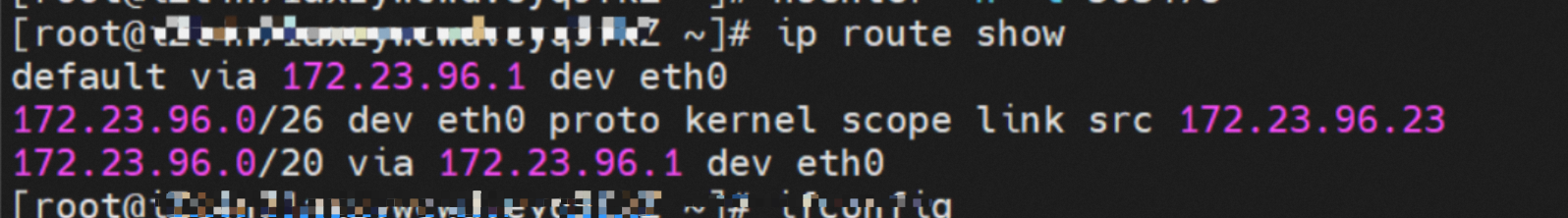
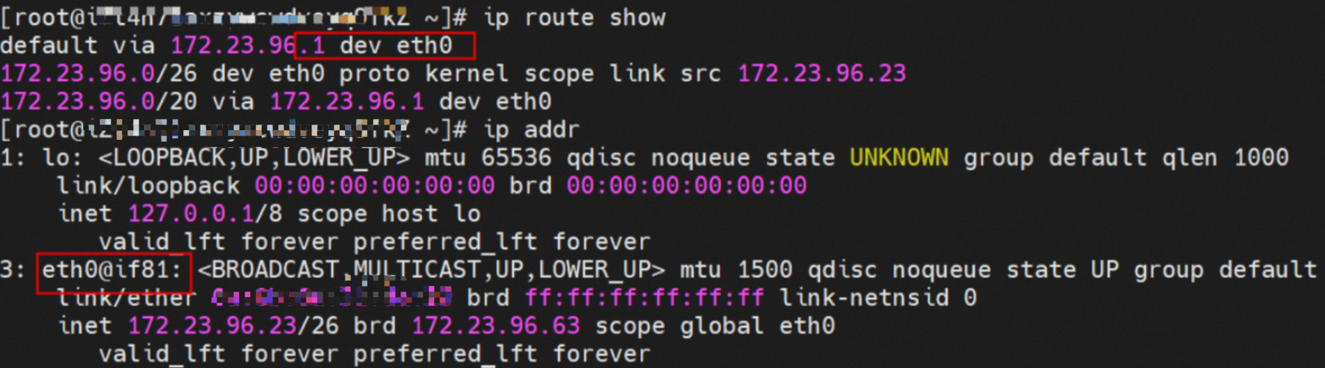
For the pod `centos-67756b6dc8-rmmxt` with the IP address 172.23.96.23, the process ID (PID) on the host is 503478. The container's network namespace has a default route that points to the container's eth0 interface.

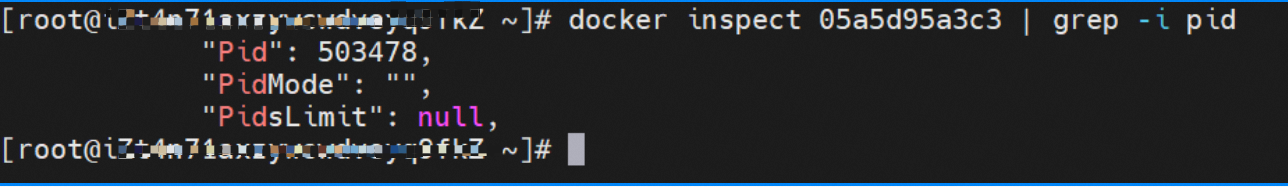
The corresponding veth pair for this container's eth0 interface in the ECS OS is `vethd7e7c6fd`.

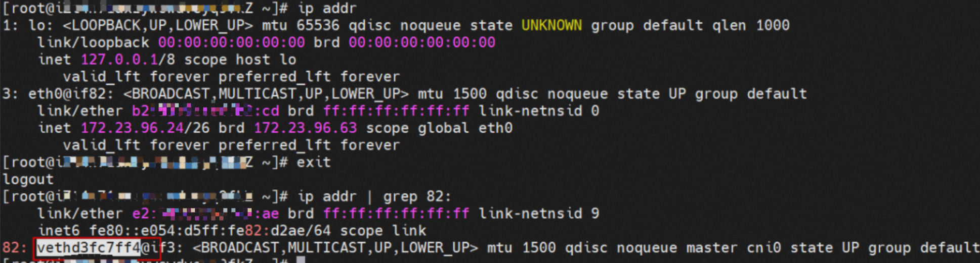
Using a similar method, you can find that for the pod `nginx-7d6877d777-6jkfg` with the IP address 172.23.96.24, the PID on the host is 2981608. The corresponding veth pair for its eth0 interface in the ECS OS is `vethd3fc7ff4`.
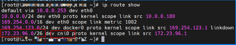
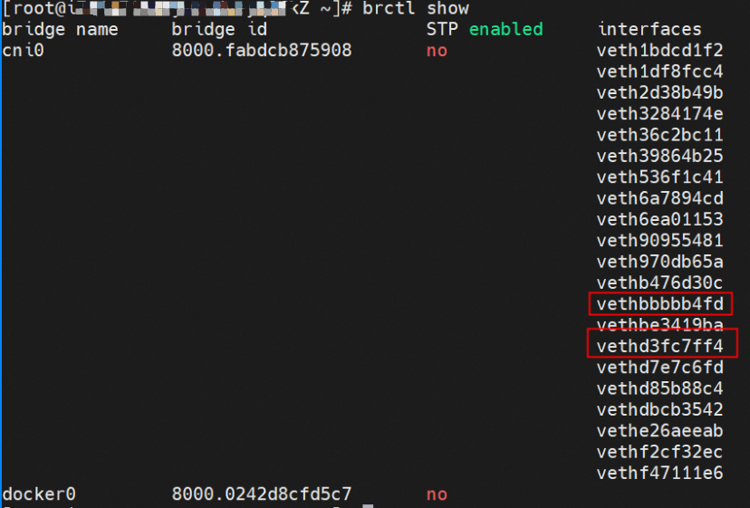
In the ECS OS, a route to the pod CIDR block exists with cni0 as the next hop. The cni0 bridge also contains information about the `vethxxx` interfaces for the two containers.
Summary
Data link forwarding diagram:
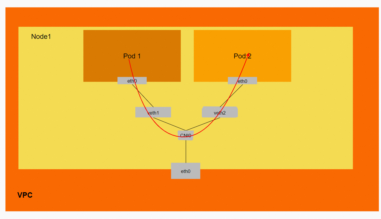
Data link: ECS1 Pod1 eth0 -> `vethxxx1` -> cni0 -> `vethxxx2` -> ECS1 Pod2 eth0.
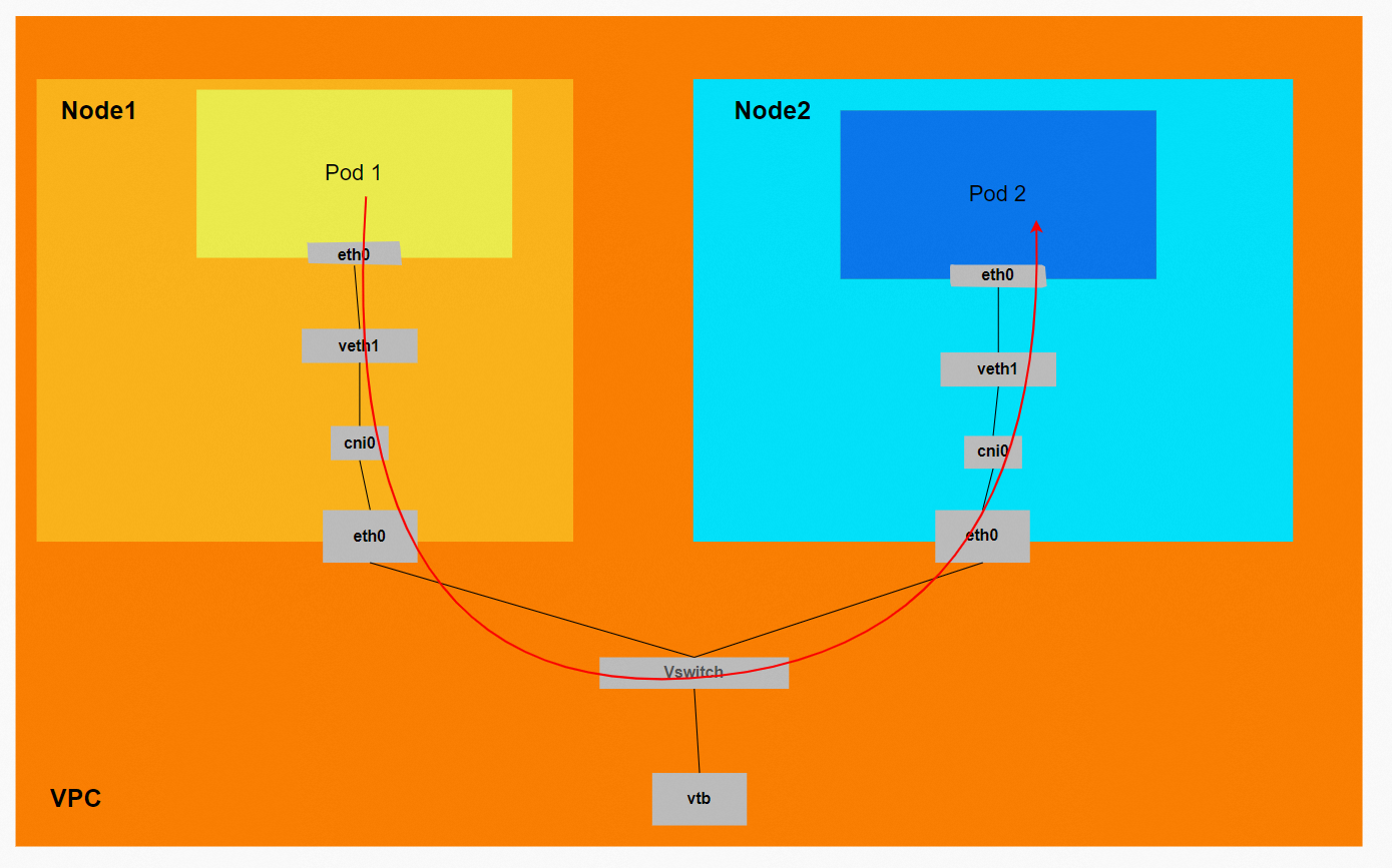
Scenario two: The client and server-side pod are on different ECS instances
This scenario includes the following sub-scenarios, which share the same data link:
A service is exposed by a pod IP address, and the client and pod are on different nodes.
A service is exposed by a Service's cluster IP address, and the client and the Service's backend pod are on different nodes.
A service is exposed by a Service's external IP address with ExternalTrafficPolicy set to Cluster. The client is inside the cluster, and the Service's backend pod is on a different node.
Environment
The xxx.10.0.0.180 node has two Pods: centos-67756b6dc8-rmmxt (IP address 172.23.96.23) and nginx1-76c99b49df-7plsr (IP address 172.23.96.163).

The `ExternalTrafficPolicy` for the nginx1 Service is set to `Cluster`.
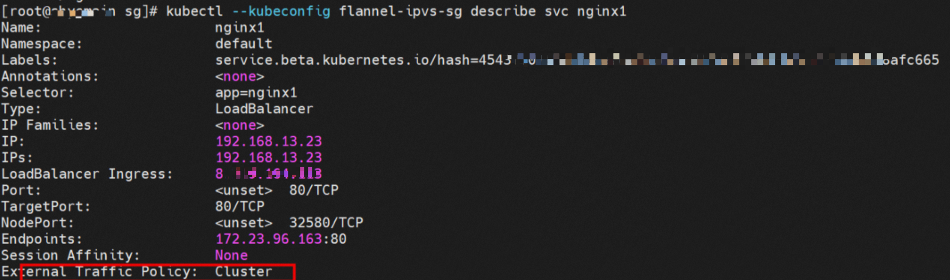
IPVS rules on the source pod's ECS instance
When the source data link accesses the Service's cluster IP address `192.168.13.23`, the traffic reaches the ECS instance's OS. It then hits an IPVS rule and is resolved to one of the Service's backend Endpoints. In this example, there is only one pod, so there is only one Endpoint.

Summary
Data link forwarding diagram:
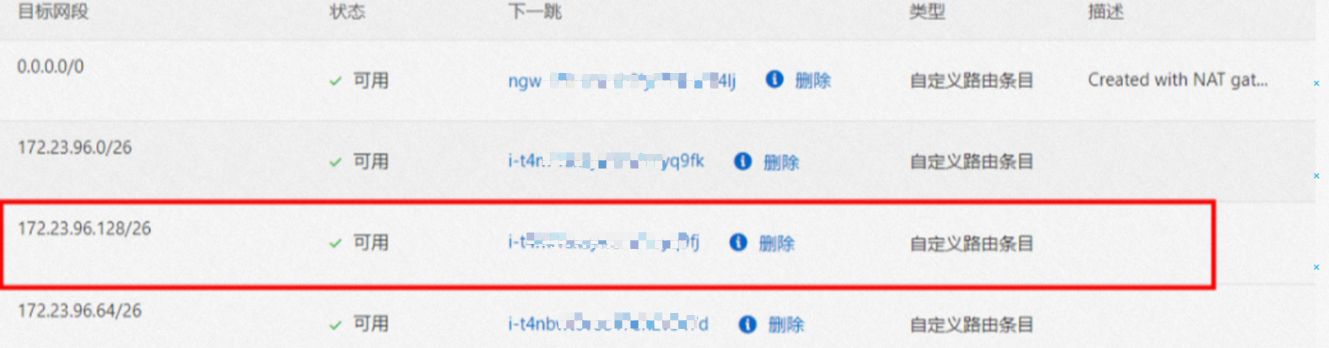
The VPC route table automatically configures a custom route entry. The destination of the entry is the pod CIDR block, and the next hop is the ECS instance to which the pod CIDR block belongs. ACK control plane components configure this rule by calling the VPC OpenAPI. You do not need to manually configure or delete it.
Conntrack table information (when accessing a Service)
Node1:
The source (src) is the source pod's IP address, and the destination (dst) is the Service's cluster IP address. The reply message is expected to come from one of the Service's Endpoints, `172.23.96.163`, back to the source pod.
![]()
Node2:
The conntrack table on the destination pod's ECS instance records that the source pod is accessing the destination pod. It does not record the Service's cluster IP address.
![]()
Data link: ECS1 Pod1 eth0 -> `vethxxx1` -> cni0 -> ECS1 eth0 -> VPC -> ECS2 eth0 -> cni0 -> `vethxxx2` -> ECS2 Pod2 eth0.
The VPC route table automatically configures a custom route entry where the destination is the pod CIDR block and the next hop is the ECS instance that owns the pod CIDR block. ACK control plane components configure this rule by calling the VPC OpenAPI. You do not need to manually configure or delete it.
If you access the Service's cluster IP address or the Service's external IP address in Cluster mode, the data link enters the ECS OS through the veth pair. It then hits the corresponding IPVS rule. Based on the load balancing rule, a backend is selected from IPVS, and the traffic is forwarded to one of the Service's backend Endpoints. The Service's IP address is captured only at the pod's eth0, the veth pair, and the `vethxxx` interface. It is not captured in other parts of the link.
Scenario three: ExternalTrafficPolicy is Local, and the client and server-side pod are on different ECS instances within the cluster
This scenario covers one type of data link: a service is exposed by a Service's external IP address with `ExternalTrafficPolicy` set to `Local`. The client is inside the cluster, and the Service's backend pod is on a different node.
Environment
The xxx.10.0.0.180 node hosts two Pods: centos-67756b6dc8-rmmxt and nginx1-76c99b49df-7plsr, with the IP addresses 172.23.96.23 and 172.23.96.163 respectively.

The `ExternalTrafficPolicy` for the nginx1 Service is set to `Local`.
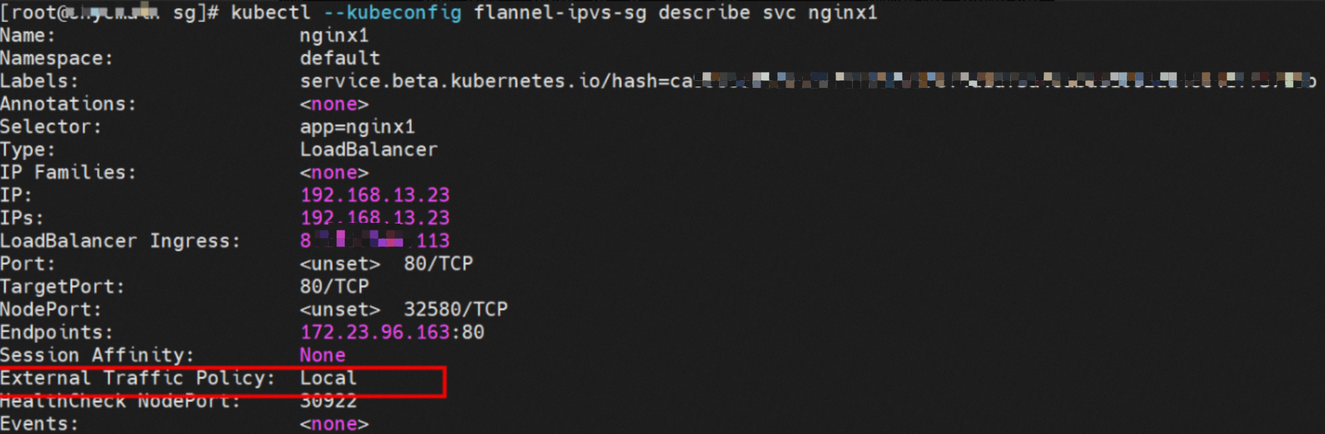
IPVS rules on the source pod's ECS instance
When the source data link accesses the Service's external IP address `8.xx.xxx.113`, the traffic reaches the ECS instance's OS and hits an IPVS rule. However, there is no Endpoint for the external IP address. Because the rule has no backend pod, the connection is refused.

Summary
Data link forwarding diagram:
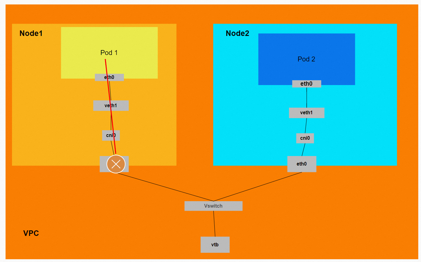
Data link: ECS1 Pod1 eth0 -> `vethxxx1` -> Connection breaks.
When you access a Service's external IP address in Local mode, the data link enters the ECS OS through the veth pair and hits the corresponding IPVS rule. However, in Local mode, the IPVS backend for the external IP address is empty. The rule has no backend to forward traffic to, so the link terminates at IPVS and the access fails. Therefore, for access from within the cluster, use the method recommended by Kubernetes: access the Service using its ClusterIP.
Scenario four: ExternalTrafficPolicy is Local, and the client is outside the cluster
This scenario covers one type of data link: a client outside the cluster accesses a Service's external IP address when `ExternalTrafficPolicy` is set to `Local`.
Environment
The nginx1 deployment has three pods. Two pods, `nginx1-76c99b49df-4zsdj` and `nginx1-76c99b49df-7plsr`, are deployed on the ECS instance `xxx.10.0.1.206`. The third pod, `nginx1-76c99b49df-s6z79`, is deployed on another node, `xxx.10.0.1.216`.

The `ExternalTrafficPolicy` for the nginx1 Service is set to `Local`.
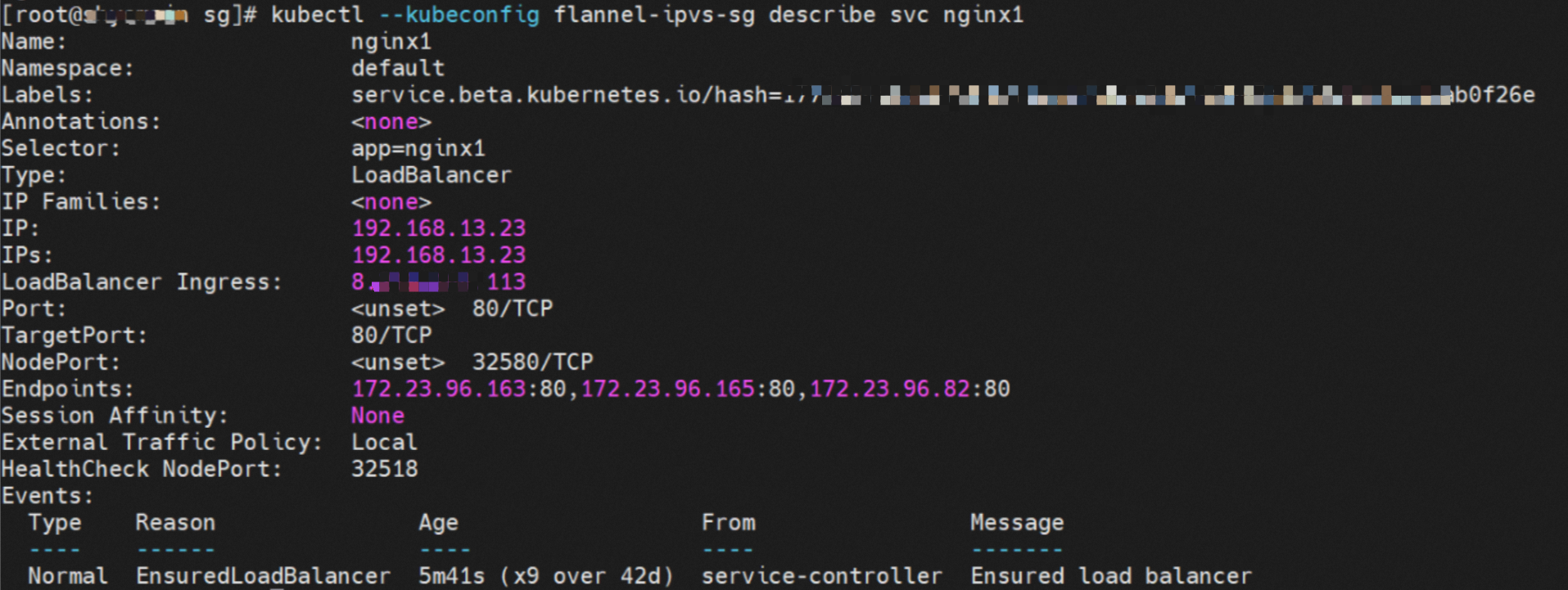
SLB configuration
The SLB backend vServer group contains only two ECS nodes: `xxx.10.0.1.216` and `xxx.10.0.1.206`. Other nodes in the cluster, such as `xxx.10.0.0.180`, are not added to the SLB backend vServer group. The IP addresses in the server group are the ECS instance IP addresses, and the port is the Service's NodePort, 32580.
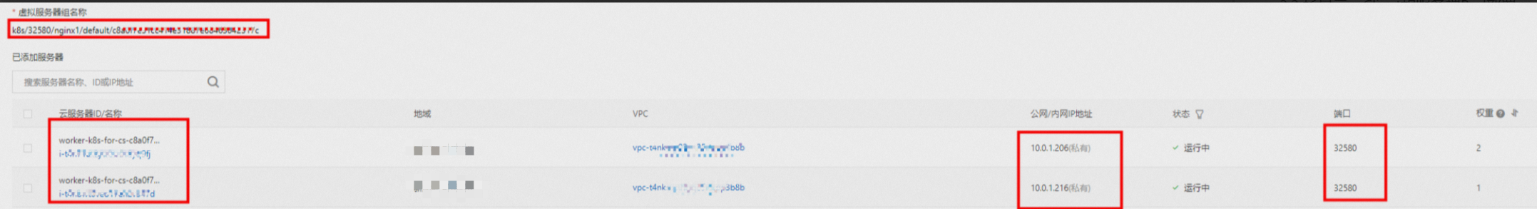
Therefore, in Local mode for `ExternalTrafficPolicy`, only the ECS nodes that host the Service's backend pods are added to the SLB backend vServer group to participate in traffic forwarding. Other nodes in the cluster do not participate.
IPVS rules on ECS instances in the SLB vServer group
The two ECS instances in the SLB vServer group show that the IPVS forwarding rules for NodeIP + NodePort are different. In Local mode for `ExternalTrafficPolicy`, only if a backend pod exists on a node will that pod's IP address be added to the node's IPVS forwarding rule. Backend pods on other nodes are not added. This ensures that traffic forwarded by SLB is sent only to pods on the same node and not forwarded to other nodes.
Node1: xxx.10.0.1.206
Node2: xxx.10.0.1.216

Summary
Data link forwarding diagram:
This diagram shows that only ECS instances with backend pods are added to the SLB backend. When you access the Service's external IP address (the SLB IP address) from outside the cluster, the data link is forwarded only to the ECS instances in the vServer group. It is not forwarded to other nodes in the cluster.
Conntrack table information
Node:
The source (src) is the external client's IP address, the destination (dst) is the node's IP address, and the destination port (dport) is the Service's NodePort. The reply packet is expected to come from the pod `172.23.96.82` on this ECS instance back to the source.

Data link: Client -> SLB -> ECS eth0 + ECS NodePort -> cni0 -> `vethxxx` -> ECS1 Pod1 eth0.
When `ExternalTrafficPolicy` is set to `Local`, only the ECS nodes that host the Service's backend pods are added to the SLB backend vServer group to participate in traffic forwarding. Other nodes in the cluster do not participate.
Scenario five: ExternalTrafficPolicy is Cluster, and the client is outside the cluster
This scenario covers one type of data link: a client outside the cluster accesses a Service's external IP address when `ExternalTrafficPolicy` is set to `Cluster`.
Environment
The nginx1 deployment has three pods. Two pods, `nginx1-76c99b49df-4zsdj` and `nginx1-76c99b49df-7plsr`, are deployed on the ECS instance `xxx.10.0.1.206`. The third pod, `nginx1-76c99b49df-s6z79`, is deployed on another node, `xxx-1.10.0.1.216`.

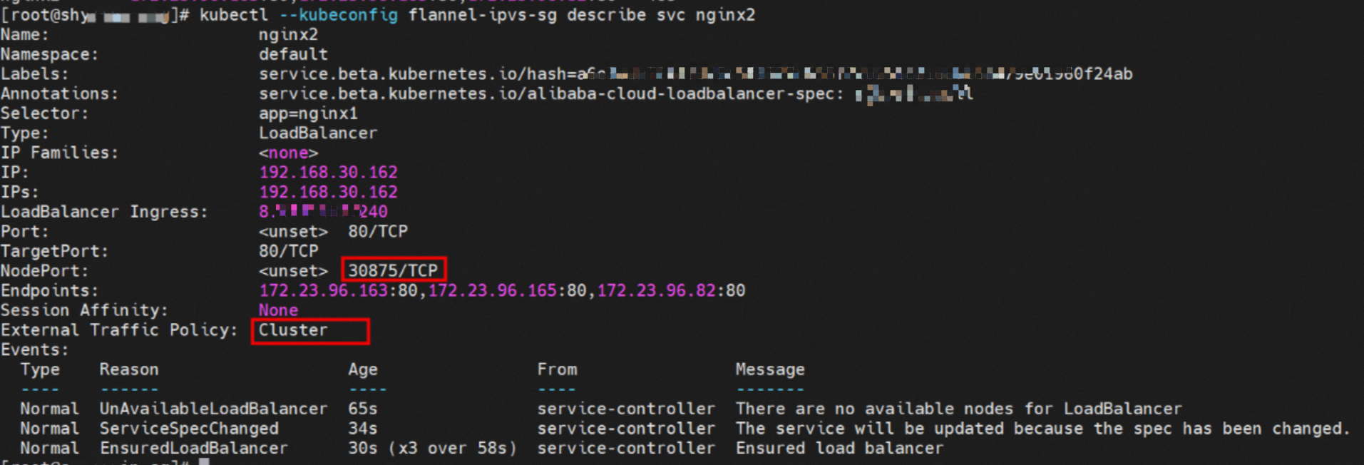
The `ExternalTrafficPolicy` for the nginx2 Service is set to `Cluster`.
SLB configuration
From the SLB console, you can see that all nodes in the cluster, `xxx-1.10.0.0.180`, `xxx-1.10.0.1.216`, and `xxx-1.10.0.1.206`, are added to the SLB vServer group. The IP addresses in the vServer group are the ECS instance IP addresses, and the port is the Service's NodePort, 30875.
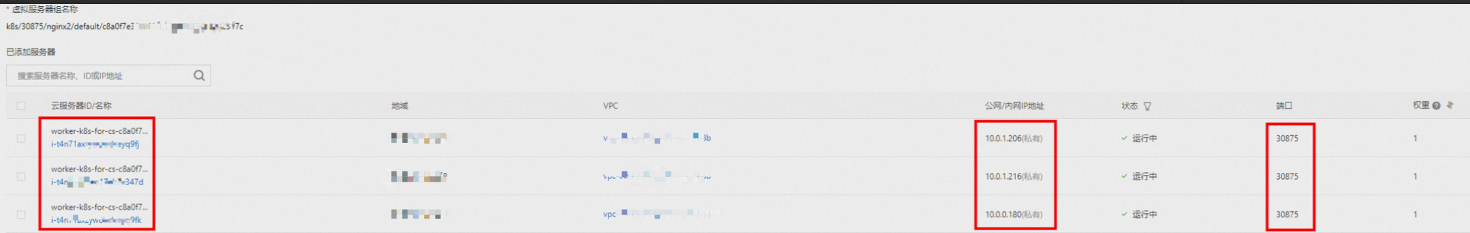
Therefore, when `ExternalTrafficPolicy` is set to `Cluster`, all ECS nodes in the cluster are added to the SLB backend vServer group to participate in traffic forwarding.
IPVS rules on ECS instances in the SLB vServer group
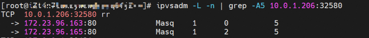
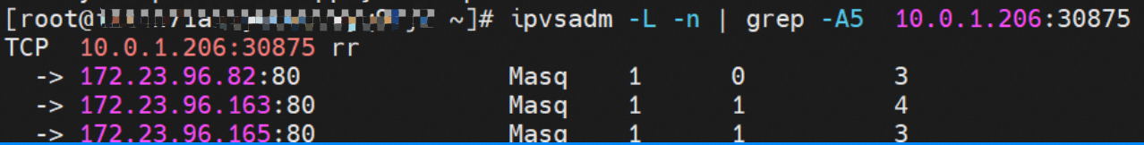
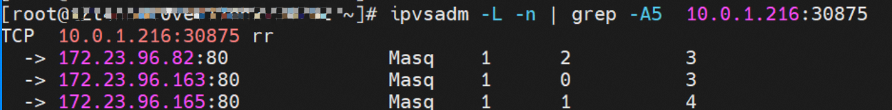
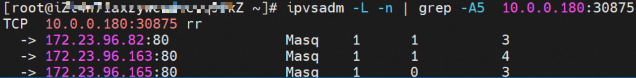
The instances in the SLB vServer group show that the IPVS forwarding rules for NodeIP + NodePort are identical. When `ExternalTrafficPolicy` is set to `Cluster`, all of the Service's backend pods are added to the IPVS forwarding rules on every node. Even if a node hosts a backend pod, traffic is not guaranteed to be forwarded to that pod. It might be forwarded to a backend pod on another node.
Node1: xxx.10.0.1.206 (This node has a backend pod)
Node2: xxx.10.0.1.216 (This node has a backend pod)
Node3:xxx.10.0.0.180 (This node has no backend pod)
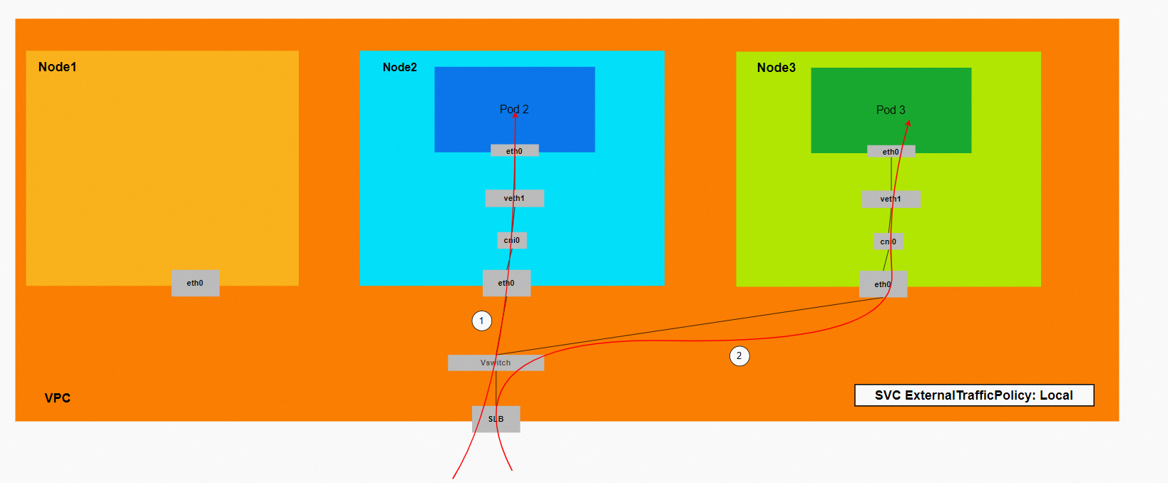
Summary
Data link forwarding diagram:
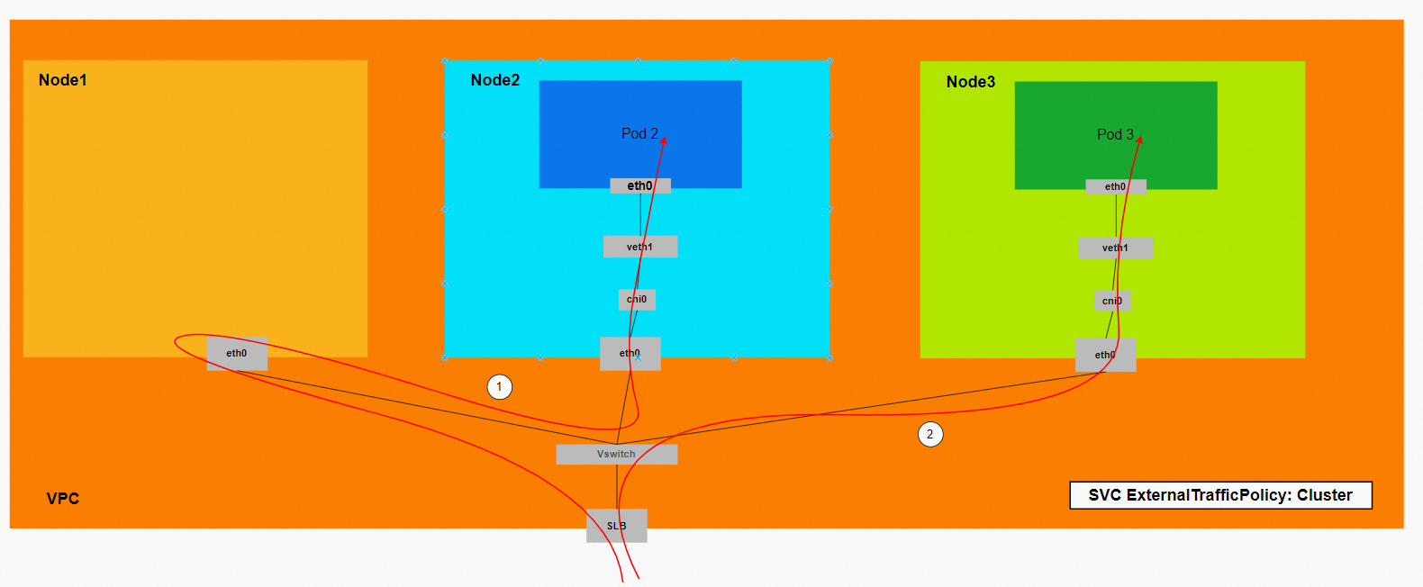
This diagram shows that all ECS instances in the cluster are added to the SLB backend. When you access the Service's external IP address (the SLB IP address) from outside the cluster, traffic might be forwarded to other nodes.
Conntrack table information
Link 1:
Node xxx.10.0.0.180:
This data link corresponds to Link 1 in the diagram. The traffic is forwarded to node `xxx.10.0.0.180`, which does not host a backend pod for the Service. The conntrack information shows the following:
The source (src) is the external client's IP address, the destination (dst) is the node's IP address, and the destination port (dport) is the Service's NodePort. The reply packet is expected to come from `172.23.96.163` back to `10.0.0.180`. From the previous information, we know that `172.23.96.163` is the IP address of `nginx1-76c99b49df-7plsr`, which is deployed on node `xxx.10.0.1.206`.

Node xxx.10.0.1.206:
The conntrack table on this node shows that the source (src) is node `xxx.10.0.0.180`, and the destination (dst) is port 80 of `172.23.96.163`. The reply packet is also sent directly back to node `xxx.10.0.0.180`.

In summary, the source address changes multiple times. Therefore, in Cluster mode, the real client IP address can be lost.
Link 2:
The source (src) is the external client's IP address, the destination (dst) is the node's IP address, and the destination port (dport) is the Service's NodePort. The reply is expected to come from the pod `172.23.96.82` on this ECS instance back to `172.23.96.65`. This address is an address within the SLB cluster.

Data links:
Scenario one: Client -> SLB -> ECS eth0 + ECS NodePort -> cni0 -> `vethxxx` -> ECS1 Pod1 eth0.
Scenario two: Client -> SLB -> ECS1 eth0 + ECS1 NodePort -> OS Routing -> ECS2 eth0 + Pod port -> cni0 -> `vethxxx` -> ECS2 Pod1 eth0.
When `ExternalTrafficPolicy` is set to `Cluster`, all Kubernetes ECS nodes are added to the SLB backend vServer group to participate in traffic forwarding. This can lead to scenarios where traffic is forwarded between multiple ECS instances within the cluster. In this situation, the real client IP address might be lost.