Connect data centers using CEN
This topic explains how to use routing policies to connect different data centers.
Prerequisites
This topic applies only to Basic Edition transit routers.
-
You have connected your on-premises data centers to Alibaba Cloud with Express Connect. For more information, see Classic Link.
-
You have created a CEN instance and attached the required network instances. For more information, see CEN instances and Attach network instances.
-
You have purchased a bandwidth plan and set inter-region bandwidth. For more information, see Use a bandwidth plan and Create inter-region connections.
Background
By default, the system adds a routing policy with a policy priority of 5000 and an action of Reject to the CEN transit router. This policy restricts communication between different Virtual Border Routers (VBRs) attached to the CEN instance. However, in specific scenarios, you may need to allow communication between these VBRs.
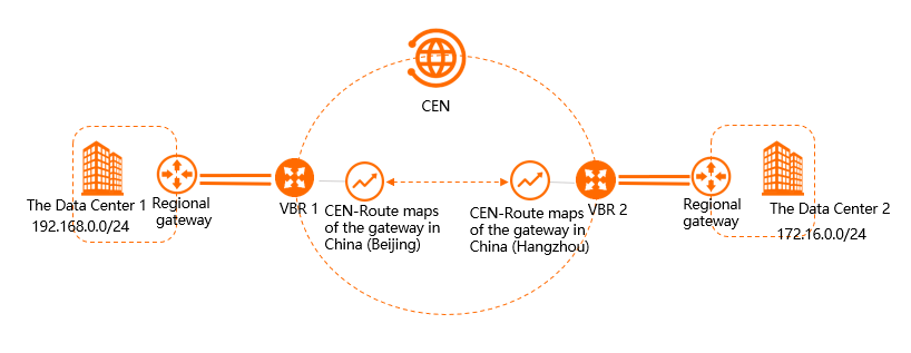
As shown in the figure, data center 1, in the China (Beijing) region, connects to Alibaba Cloud via VBR1. Data center 2, in the China (Hangzhou) region, connects via VBR2. Both VBRs are attached to the same CEN instance. By default, communication between data center 1 and data center 2 is blocked. To enable this communication, configure routing policies to connect VBR1 and VBR2.
Step 1: Configure data center 1 to 2 routing
-
Log on to the CEN console.
-
On the CEN Instance page, find the target CEN instance and click the instance ID.
-
On the details page of the CEN instance, click the ID of the transit router in the desired region.
-
On the details page of the transit router, click the Route Table tab, and then click Routing Policy.
-
On the Routing Policy tab, click Add Route Map. Configure the routing policy as follows and click OK.
-
Policy Priority: The priority of the routing policy. A smaller value indicates a higher priority. In this example, enter 20.
-
Description: (Optional) The description of the routing policy.
-
Region: The region where the routing policy applies. In this example, select China (Beijing).
-
Policy Direction: The direction of traffic to which the policy applies. In this example, select RegionOut.
-
Match Condition: The match conditions for the routing policy. In this example, add the following two conditions:
-
Source Instance IDs: The VBR2 instance ID.
-
Destination Instance IDs: The VBR1 instance ID.
-
-
Policy Action: The action to take on matching routes. In this example, select Allow.
After adding the routing policy, navigate to the Network Instance Route Table tab. On the Network Routes tab of the transit router, find the route to the destination CIDR block
172.16.0.0/24. A View Details link appears in the Policy Matched column, indicating that the route matches the configured routing policy. The route's type is CEN, its status is Available, and its next hop is China (Hangzhou). -
Step 2: Configure data center 2 to 1 routing
-
In the left-side navigation pane, click CEN Instance.
-
On the CEN Instance page, find the target CEN instance and click the instance ID.
-
On the details page of the CEN instance, click the ID of the transit router in the desired region.
-
On the details page of the transit router, click the Route Table tab, and then click Routing Policy.
-
On the Routing Policy tab, click Add Route Map. Configure the routing policy as follows and click OK.
-
Policy Priority: The priority of the routing policy. A smaller value indicates a higher priority. In this example, enter 20.
-
Description: (Optional) The description of the routing policy.
-
Region: The region where the routing policy applies. In this example, select China (Hangzhou).
-
Policy Direction: The direction of traffic to which the policy applies. In this example, select RegionOut.
-
Match Condition: The match conditions for the routing policy. In this example, add the following two conditions:
-
Source Instance IDs: The VBR1 instance ID.
-
Destination Instance IDs: The VBR2 instance ID.
-
-
Policy Action: The action to take on matching routes. In this example, select Allow.
After adding the routing policy, navigate to the Network Instance Route Table tab. On the Network Routes tab, you can find the route to the destination CIDR block
192.168.0.0/24. The route type is CEN, its status is Available, and its next hop is China (Beijing). A View Details link appears in the Policy Matched column. -
Step 3: Test connectivity
-
Open the command prompt on a PC in data center 1.
-
Run the ping command and ping the IP address of a PC in data center 2 to verify connectivity.
The output confirms that the PC in data center 1 can access the PC in data center 2.
C:\Users\Administrator>ping 172.16.0.1 Pinging 172.16.0.1 with 32 bytes of data: Reply from 172.16.0.1: bytes=32 time<1ms TTL=128 Reply from 172.16.0.1: bytes=32 time<1ms TTL=128 Reply from 172.16.0.1: bytes=32 time<1ms TTL=128 Reply from 172.16.0.1: bytes=32 time<1ms TTL=128 Ping statistics for 172.16.0.1: Packets: Sent = 4, Received = 4, Lost = 0 (0% loss), Approximate round trip times in milli-seconds: Minimum = 0ms, Maximum = 0ms, Average = 0ms -
Open the command prompt on a PC in data center 2.
-
Run the ping command to ping the IP address of the PC in data center 1 to verify connectivity.
The output confirms that the PC in data center 2 can access the PC in data center 1.
C:\Users\Administrator>ping 192.168.0.1
Pinging 192.168.0.1 with 32 bytes of data:
Reply from 192.168.0.1: bytes=32 time<1ms TTL=128
Reply from 192.168.0.1: bytes=32 time<1ms TTL=128
Reply from 192.168.0.1: bytes=32 time<1ms TTL=128
Reply from 192.168.0.1: bytes=32 time<1ms TTL=128
Ping statistics for 192.168.0.1:
    Packets: Sent = 4, Received = 4, Lost = 0 (0% loss),
Approximate round trip times in milli-seconds:
    Minimum = 0ms, Maximum = 0ms, Average = 0ms