Logic group configuration
A logic group is a system that lets you visually encapsulate and reuse the interaction logic of connected nodes. Use logic groups to build data-driven, dynamic interactive effects. This topic describes the core features of logic groups, including how to add, configure, and manage them.
Usage notes
Logic nodes and logic groups added to the main canvas are linked by reference. If you change the name or content of a logic group, all corresponding logic nodes on the main canvas are affected.
Prerequisites
You have created a data dashboard. You can create a dashboard from a template, from a blank canvas, or using AI.
Open a logic group
Access the DataV console.
On the All Applications page, hover over the target dashboard and click Edit.
On the dashboard editor page, click the
 icon in the top menu bar to open the blueprint editor. In the navigation pane on the left side of the main canvas, click Logic Group to display the logic group configuration.
Before you configure a logic group, familiarize yourself with the layout and operations of the blueprint editor.
Add a logic group
In the blueprint editor, click . This adds an Input widget and an Output widget to the logic group canvas.
Optional: Click the Input widget to add an input anchor point in the anchor point configuration panel on the right. Click the Output widget to add an output anchor point in the same panel.
In the navigation pane on the left, click Logic Node to go to the Logic Node page, where you can add nodes, such as a serial data processing node.
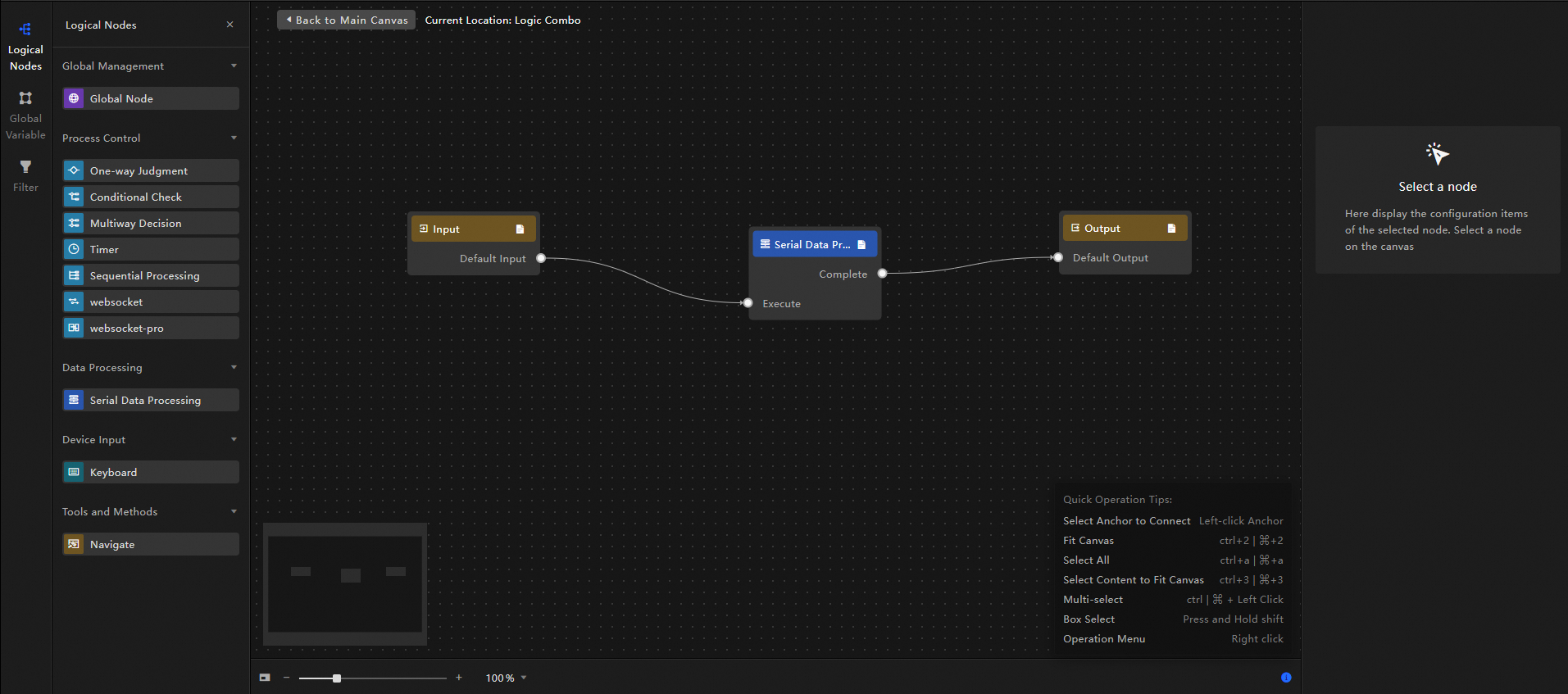
Connect the nodes and set the data processing method as shown in the following figure to complete the logic group.
At the top of the canvas, click Back to Main Canvas to return to the main canvas editor.
Manage logic groups
Rename a logic group
On the logic group page, hover over the target logic group and click the  icon to rename it.
Delete a logic group
On the logic group page, hover over the target logic group and click the  icon to delete it.
A logic group cannot be recovered after it is deleted. Proceed with caution.
Drill down into a logic group
On the logic group page, hover over the target logic group and click the  icon to drill down into its canvas.
Add to the main blueprint canvas
On the logic group page, hover over the target logic group and click the  icon to add it to the main blueprint canvas.
Use a logic group
Add the required layer nodes to the main canvas. This example uses a ticker board node and a column chart node.
Click the
 icon in the top menu bar to open the blueprint editor. Then, add the layer nodes to the blueprint canvas.
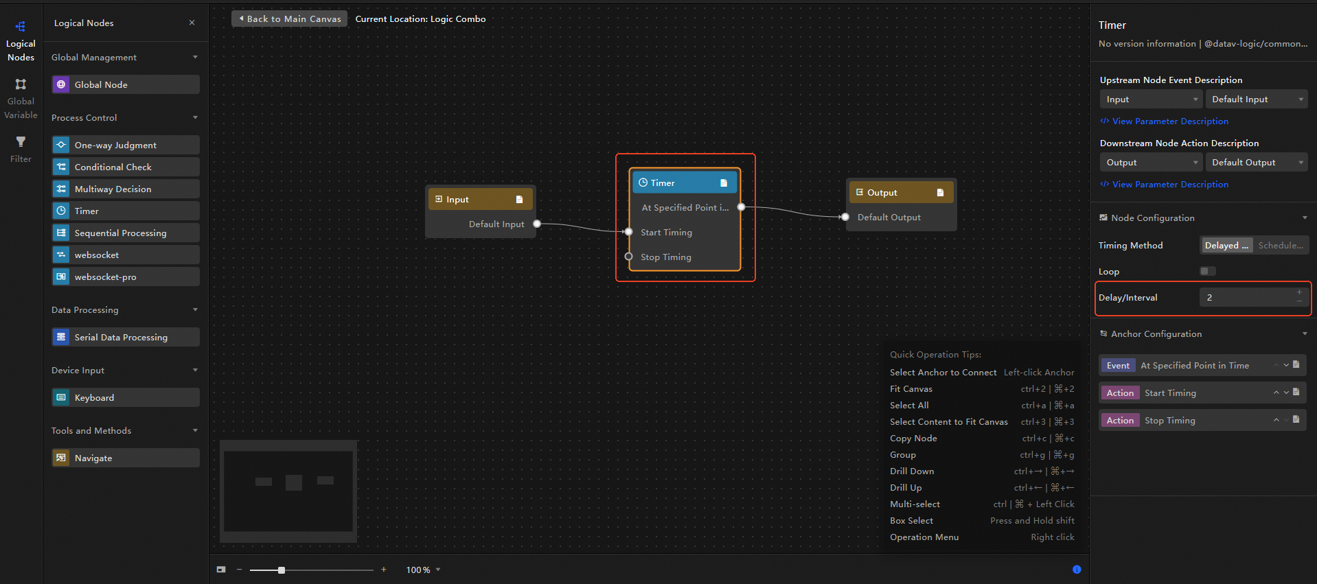
In the blueprint editor, click to open the logic group canvas. Configure the logic nodes for the group, for example, by adding a timer node and setting the delay to 2 seconds.
After completing the configuration, click Back to Main Canvas to return to the main blueprint canvas editor.
In the logic group list, click the
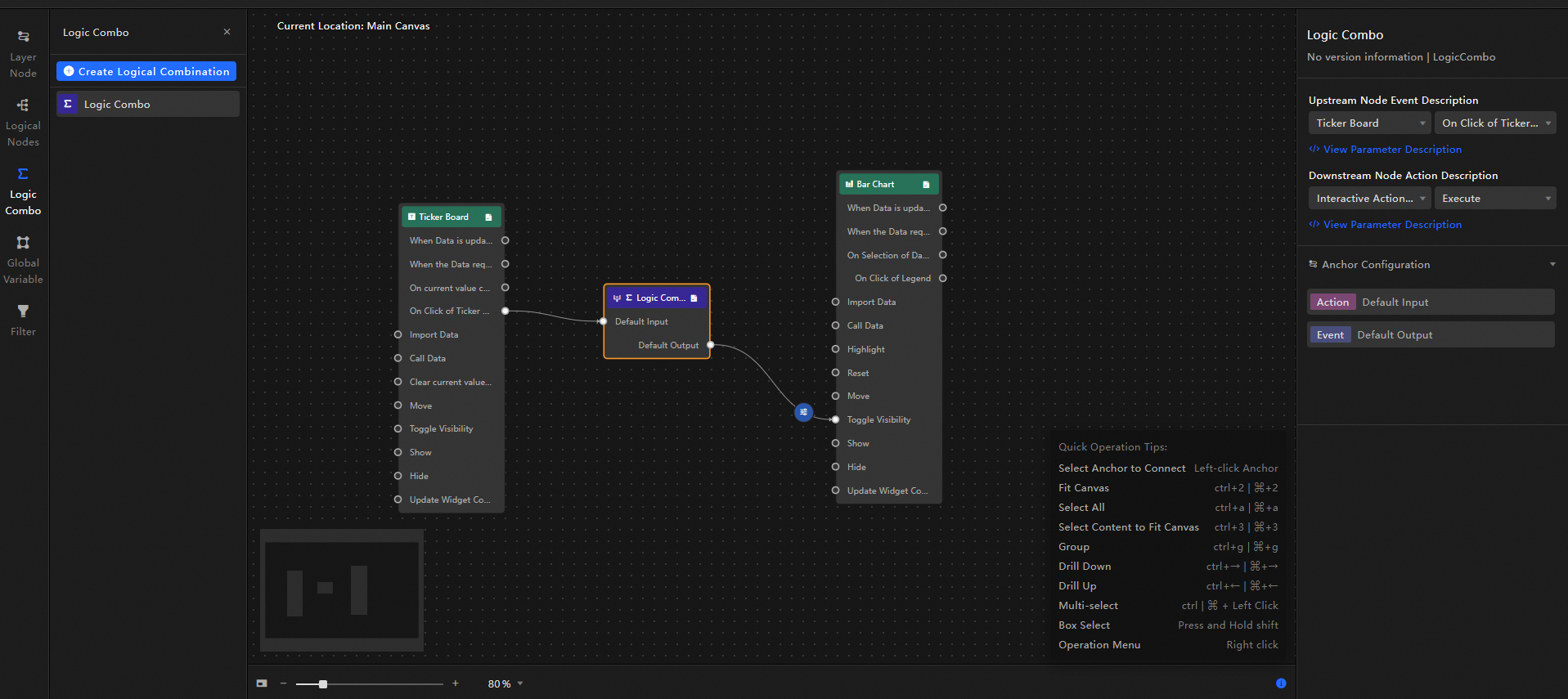
icon to add the completed logic group to the main blueprint canvas.Configure the blueprint editor on the main canvas as shown in the following figure:
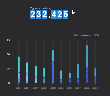
Effect: When you click the ticker board, the timer starts. After 2 seconds, the timer stops and the visibility of the column chart is toggled.
Preview or publish the current data dashboard to view the interactive effect.
 icon in the top menu bar to open the blueprint editor. Then, add the layer nodes to the blueprint canvas.