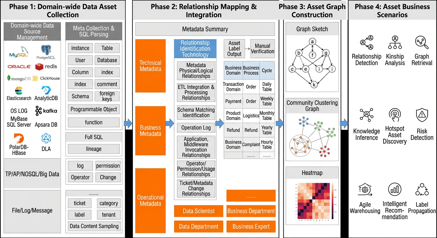
The enhanced Entity Relationship (E-R) feature of Data Management DMS visualizes the relationships among data assets in your databases. This feature is built on core capabilities, such as a proprietary unified Catalog metadata acquisition engine, a column-level operator lineage parsing engine that analyzes the associations, dependencies, and impacts between fields, and data asset knowledge graph construction. This topic describes the advantages, scenarios, and usage of the enhanced E-R feature.
Prerequisites
Supported database instance types: RDS MySQL, RDS PostgreSQL, RDS MariaDB, PolarDB for MySQL, PolarDB for PostgreSQL, AnalyticDB for MySQL, and AnalyticDB for PostgreSQL.
The database instance is in one of the following regions: China (Hangzhou), China (Beijing), China (Shanghai), China (Shenzhen), China (Zhangjiakou), China (Qingdao), China (Chengdu), China (Hohhot), China (Heyuan), China (Ulanqab), China (Guangzhou), China (Nanjing-Local Region-decommissioning), or China (Fuzhou-Local Region-decommissioning).
The control mode of the database instance is Security Collaboration. For more information about control modes, see Control modes.
Background information
An Entity Relationship Diagram (E-R diagram) is a model that describes entities, properties, and relationships. During the database schema design phase, you can draw an E-R diagram. Then, you can convert the E-R diagram into multiple database tables that store primary and foreign keys. An E-R diagram effectively describes the relationships within business data and the dependencies and associations between database tables and fields. These relationships help you incorporate the logical relationships of business or database storage into the database design.
As businesses grow, the performance of database foreign keys can decrease. Many systems now manage business dependencies at the application level. This means foreign key information is often not stored in the database design. This makes it difficult to understand the logical relationships between data tables by examining the database's foreign keys. This also makes it harder to map the true logical relationships between your tables.
The enhanced E-R feature of Data Management DMS clearly displays the associations, dependencies, and impacts among business data, database tables, and fields. It also incorporates these relationships into the database design as logical relationships in the table schema.
Scenarios
Quickly understand the relationships between data in a database.
Export enhanced E-R diagrams to use as materials for project data design.
View how sensitive data is transmitted to prevent data leaks after secondary processing.
Identify the risks of data changes early by viewing data dependencies.
Use data associations to help build wide tables in a data warehouse.
View data transformation relationships to understand the data transformation pipeline.
Identify cold and hot data assets in the database by viewing data reference relationships.
Notes
You can view the E-R diagram one day (T+1) after you enable this feature.
The enhanced E-R feature only detects information about tables and fields that are entered into or changed in DMS. It displays the associations, impacts, and dependencies among them on the page. The feature cannot detect information entered or changed from other sources, such as program code.
Billing
This feature is free of charge. However, it is only available for instances that use the Security Collaboration control mode. The Security Collaboration control mode is a paid service.
Advantages
The enhanced E-R feature of DMS differs from traditional E-R diagram construction methods. In addition to traditional E-R capabilities, it uses a proprietary unified Catalog metadata acquisition engine, a column-level operator lineage parser, and data asset knowledge graph construction capabilities. These capabilities help you discover more potential relationships among data assets.
DMS has built an asset graph with over tens of billions of data nodes and relationships. It integrates various data asset business scenarios and provides related query and visualization services.
Usage
Traditional E-R
DMS provides traditional E-R capabilities and can build E-R diagrams based on physical foreign keys in a database. The following steps describe how to create a traditional E-R diagram.
Log in to DMS 5.0.
On the home page, click Database Instances on the left and select the target instance from the instance list.
Click the target instance and then double-click the target database name to go to the SQL Console page.
On the SQL Console page, create test data. The tables are ods_huiyuan_t1 (t1), ods_huiyuan_t2 (t2), ods_huiyuan_t3 (t3), ods_huiyuan_t4 (t4), and ods_huiyuan_fk. To do this, execute the following SQL statements:
One day later (T+1), you can view the enhanced E-R diagram on the SQL Console page. For more information, see View the enhanced E-R diagram.
In addition, DMS provides capabilities for column-level operator lineage parsing, task orchestration. You can use these three capabilities to implement the enhanced E-R feature of DMS. The following sections describe these three methods and their procedures.
E-R based on column-level operator lineage parsing
E-R diagrams based on column-level operator lineage parsing are built using the proprietary column-level operator lineage parser of DMS. This method can incorporate the associations, dependencies, and impacts between fields into the E-R graph. The following steps describe how to use this capability to create an enhanced E-R diagram.
On the SQL Console page, associate the IDs of the ods_huiyuan_t1 and ods_huiyuan_t3 tables to generate a wide table by executing the following SQL statement:
On the SQL Console page, perform data transformation on t4 to generate a new table named depend by executing the following SQL statements:
On the SQL Console page, perform data transformation on t2 and t3, associate the transformed data, and then generate a new table named influ by executing the following SQL statements:
One day later (T+1), you can view the enhanced E-R diagram on the SQL Console page. For more information, see View the enhanced E-R diagram.
The following sample SQL statement and table explain the principles and capabilities of E-R diagrams that are based on column-level operator lineage parsing, including the association, impact, and dependency relationships between fields.
CREATE TABLE user_trade AS
SELECT  a.user_id
        ,a.user_name
        ,a.gender
        ,b.amt
        ,b.cnt
FROM    (
            SELECT  user_id,user_name,gender
            FROM    user
            WHERE   user_type = 'taobao'
        ) a
LEFT OUTER JOIN    (
                       SELECT  user_id,sum(amt) AS amt,sum(1) as cnt
                       FROM    trade
                       WHERE   is_pay = 1
                       GROUP BY user_id
                   ) b
ON      a.user_id = b.user_id;
Relationship type |
Description |
Example |
Association between fields |
The join condition between tables contains a field association. |
In the sample SQL statement, the user_id field in the user table is associated with the user_id field in the trade table. |
Dependency between fields |
The source table and field from which the destination field originates. |
In the sample SQL statement, the user_id field in the user_trade table originates from the user_id field in the user table. |
Impact between fields |
The impact of a WHERE clause field in the source table on a field in the destination table. |
In the sample SQL statement, the is_pay field in the trade table impacts the amt field in the user_trade table. The condition is |
E-R based on task orchestration
E-R diagrams based on task orchestration use the scheduling lineage feature of task orchestration to build the asset graph. The following steps describe how to use this capability to create an enhanced E-R diagram.
Use the task orchestration feature of DMS to create a single-instance SQL node and set the scheduled time to 00:00 every day.
In the SQL editor of the task node, enter the following SQL statements:
One day later (T+1), you can view the enhanced E-R diagram on the SQL Console page. For more information, see View the enhanced E-R diagram.
View the enhanced E-R diagram
Log in to DMS 5.0.
On the home page, click Database Instances on the left and select the target instance from the instance list.
Click the target instance and then double-click the target database name to go to the SQL Console page.
In the upper-right corner of the page, click the
 icon to go to the E-R Analysis page and view the enhanced E-R diagram.
On the E-R Analysis page, you can perform the following operations:
Click a table to view its details.
Click an edge between tables to view the relationship details.