LoRaWAN Smart Toilet
This tutorial shows you how to build a LoRaWAN-connected smart toilet demo using Alibaba Cloud IoT Platform. IoT Platform provides a centralized development environment and can directly call Link WAN network management services.
Background information
Application overview
This non-intrusive smart toilet solution is designed to improve toilet usage efficiency, reduce waiting times, and enhance cleaning efficiency. Infrared pyroelectric sensors are used to detect occupancy at each stall. The real-time status is displayed on a web page or mobile app. The solution also monitors odor levels and notifies cleaners when a specified threshold is exceeded.
Bill of materials
HuiLianWuXian G200 LoRaWAN gateway
HuiLianWuXian LoRa infrared sensor
A computer with an internet connection
Step 1: Configure the LoRaWAN gateway—Build your own LoRaWAN network
Purchase a gateway from the Alibaba Cloud IoT Marketplace and set up your network.
The following gateways are used in this tutorial:
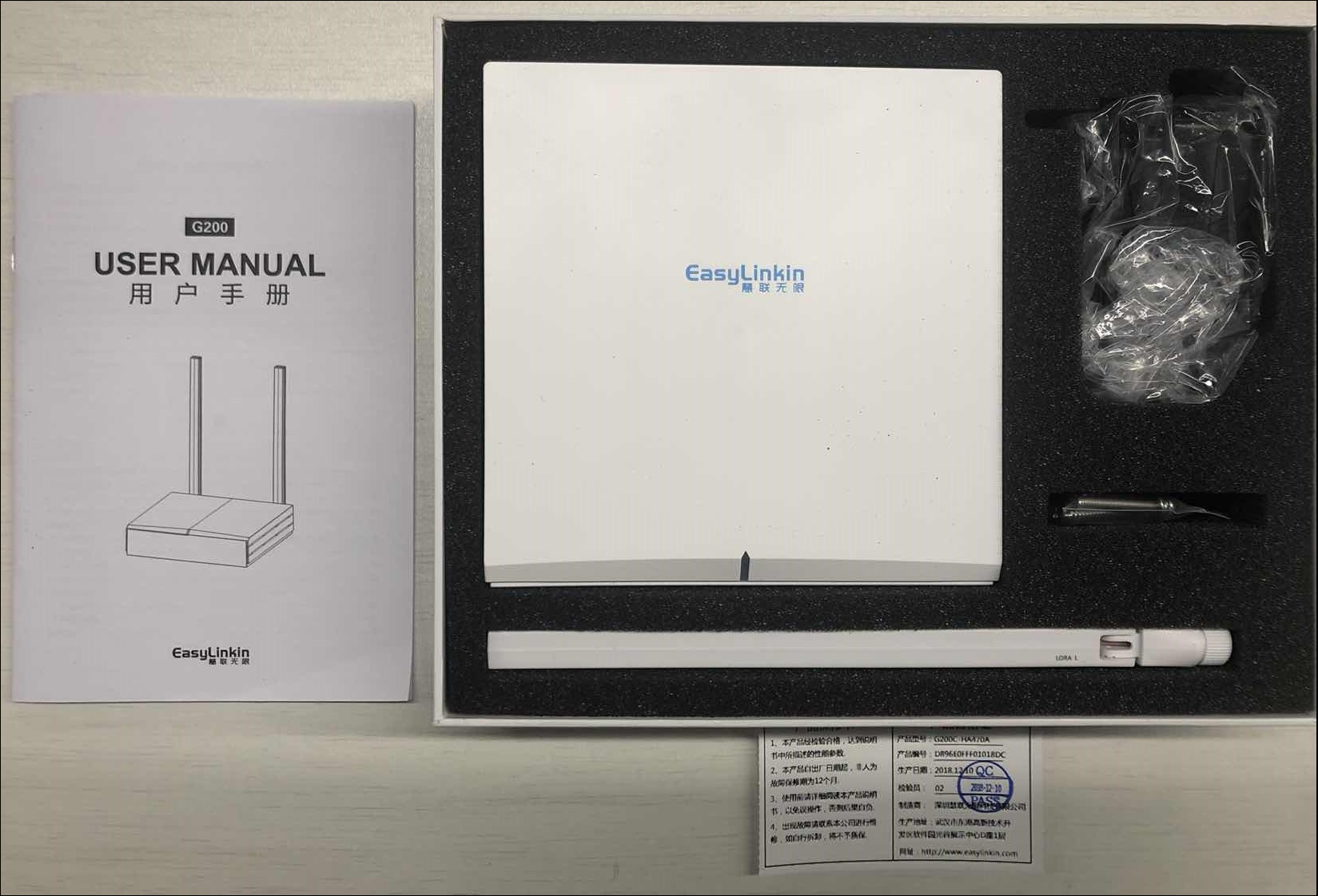
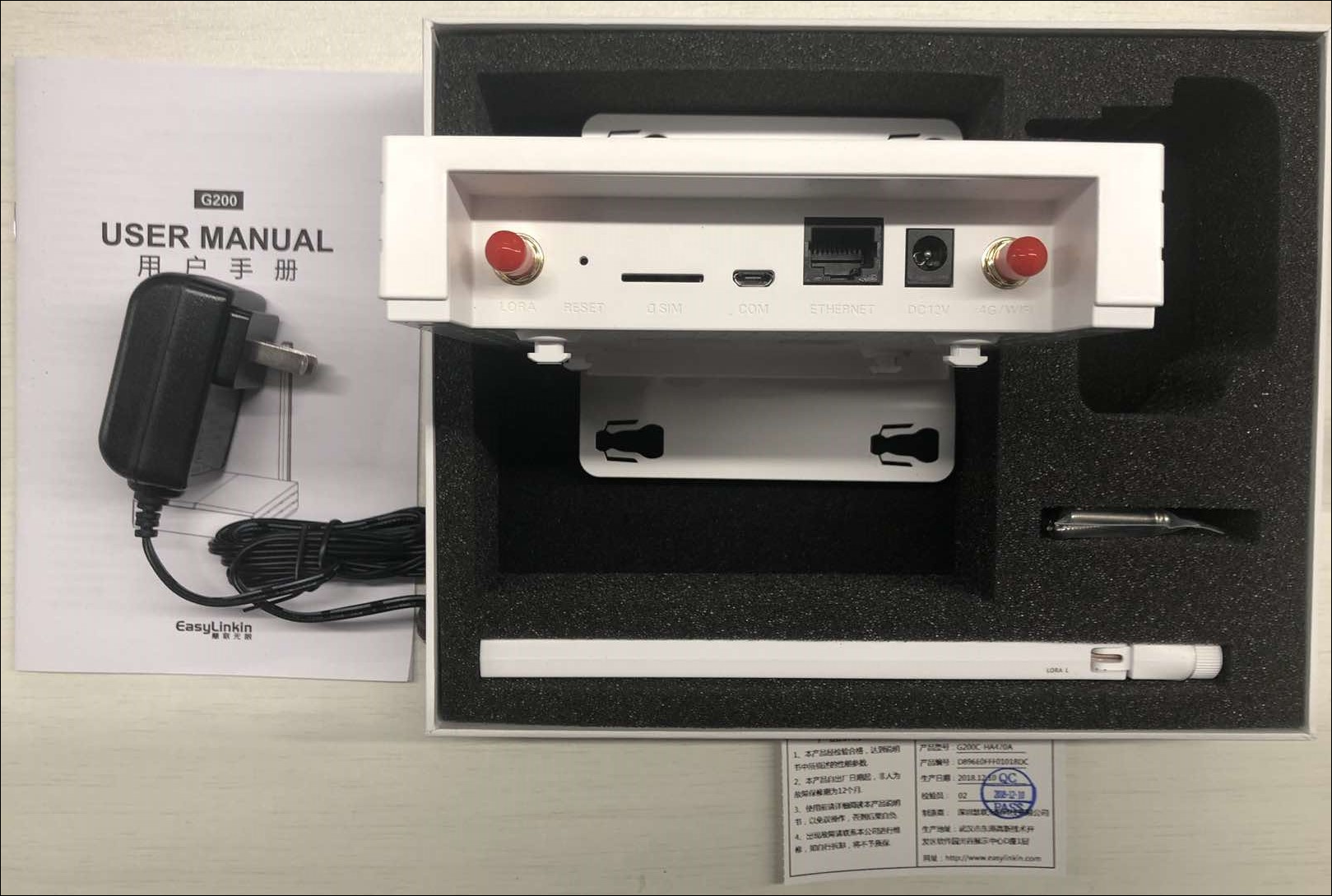
Connect the Ethernet cable and power supply. Log on to the Alibaba Cloud Link WAN console to register the gateway.
In the navigation pane on the left, choose Network Management > Gateway Management.
On the Gateways tab, click Add Gateway.
Configure the following parameters to activate the gateway.
Parameter
Setting
Description
Basic information
Name
Enter a gateway name. The name can contain letters, digits, underscores, and Chinese characters. It must be 4 to 30 characters long. Each Chinese character counts as two characters.
PIN Code
The PIN Code is a 6-digit number, usually printed on the gateway label.
Communication mode
Choose between full-duplex and half-duplex. This example uses half-duplex.
GwEUI
Check this parameter on the gateway label.
Frequency band
Select one of the following frequency bands:
CN470 same-frequency
CN470 different-frequency
AS923 same-frequency
This example uses CN470 different-frequency.
Gateway description
Optional. Add notes about the gateway. The description cannot exceed 100 characters.
Location Information
Region
Select the region where the gateway is located.
NoteYou must manually set the location because the G200 does not have a GPS module. The location appears on the map after you enter it. Gateways with GPS automatically refresh their location after reporting data.
Location details
Enter the exact location of the gateway. You can also click the map on the right to set the location.
The G200 gateway uses Dynamic Host Configuration Protocol (DHCP) by default. If you use a static IP address or Point-to-Point Protocol over Ethernet (PPPoE), you must adjust the settings based on your environment. For more information, see the G200 gateway manual. After the gateway is configured, its status changes to online in the Gateways list.Create network credentials and assign them to your account. After the credentials are assigned, you can use them to access the network.
In the navigation pane on the left, choose Network Management > Network Access.
On the Network Access page, click Add Dedicated Credential.
Configure the parameters as shown in the following figure. After the configuration is complete, click Confirm to create a credential.
Parameter
Description
Credential name
Enter a credential name. The name can contain letters, digits, underscores, and Chinese characters. It must be 4 to 30 characters long. Each Chinese character counts as two characters.
Frequency band
The following three frequency bands are available:
CN470 same-frequency
CN470 different-frequency
AS923 same-frequency
This example uses CN470 different-frequency.
Class
Select one of the following classes:
A
B
C
This example uses A, which sends data on demand.
RxDelay
If you select Class A, you can configure RxDelay to set the receive window delay after an uplink. The default is 1 second. Valid values range from 1 to 15 seconds.
In the Actions column of the credential, click Authorize Credential to authorize your account, as shown in the following figure.
After the authorization is successful, the new credential appears in the Credential List. If another user authorizes a credential to you, the credential appears in the list after you accept the authorization.
Step 2: Unpack the LoRaWAN hardware
When you unpack a certified LoRa sensor purchased online, you will find a 16-character sticker on the back. This is the DevEUI of the node. You will also see a 6-digit PINCODE field.
By default, the sensor operates in 5-minute mode. In this mode, the sensor ignores subsequent events for 5 minutes after it detects an event. This behavior is not suitable for toilet usage scenarios. You must switch the sensor to test mode to ensure that every detected event is uploaded.
To do this, open the back cover, move the jumper to the ON position, and close the cover. Do not remove the plastic tab yet.
Step 3: Configure the LoRa node on IoT Platform
Log on to the IoT Platform console.
In the left navigation pane, select Device Management Product and click Create Product.
Enter the product information and click Save.
Parameter
Description
Product name
Test device (customizable).
Category
Select Custom Category.
Node type
Select Directly Connected Device.
Connection method
Select LoRaWAN.
Network credential
Select from the list or click Add Dedicated Credential.
NoteConfirm that you have obtained a network credential in Link WAN.
Data format
Pass-through/Custom.
Product description
Optional. Describe the product.
If this is the first time you are using Link WAN, you must grant data permissions by clicking Agree to Authorization.
After the product is created, click Manage Devices to proceed.
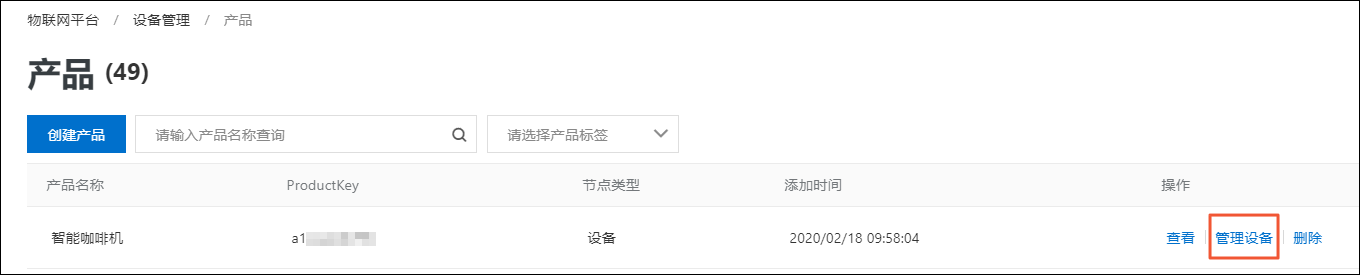
Click Add Device to connect the LoRa device.
Enter the 16-character DevEUI as the DeviceName. The DeviceName must be in lowercase.
Step 4: View uplink and downlink data and data logs
Return to the Alibaba Cloud Link WAN console to view the uplink and downlink data of the LoRaWAN link layer.
In the navigation pane on the left, choose Node Management > Node Groups.
NoteThis node is already authorized for use with IoT Platform. Therefore, you have only view permissions.
In the Actions column of the node, click View and select the Uplink Data tab to view the uplink data.
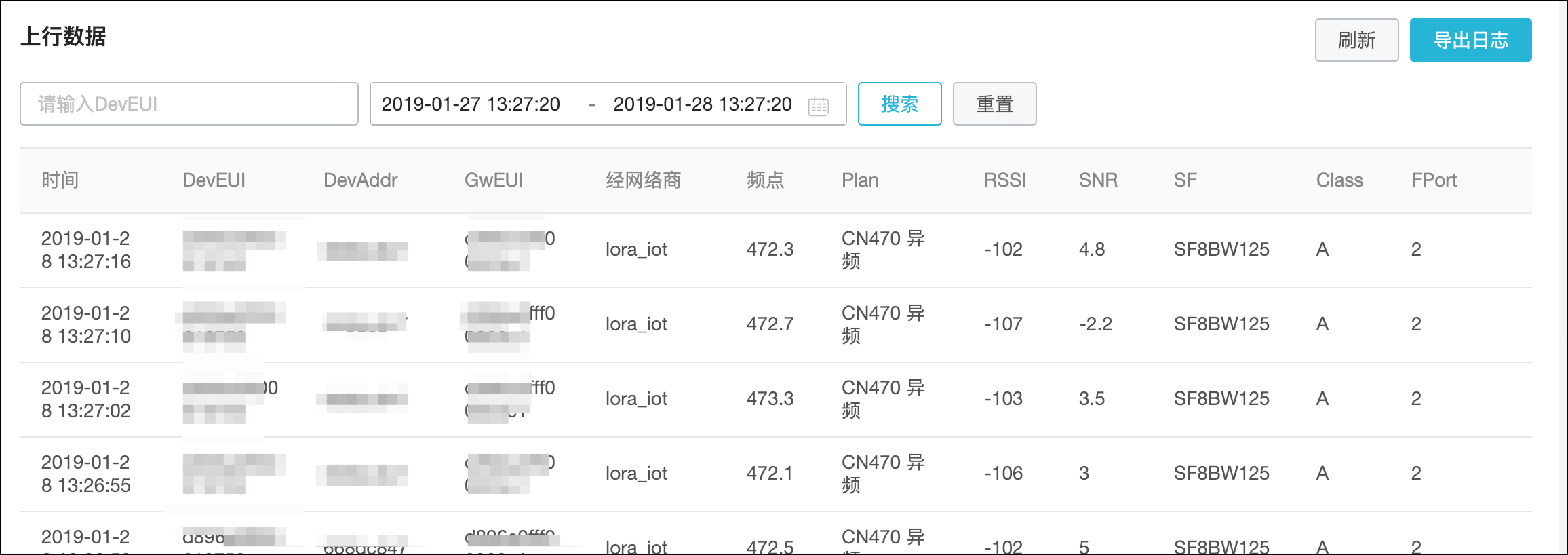
Remove the plastic tab from the LoRa sensor to power it on.
View the uplink logs in IoT Platform.
In the IoT Platform console, choose Monitoring and O&M > Simple Log Service in the navigation pane on the left. On the Uplink Message Analysis tab, view the logs.
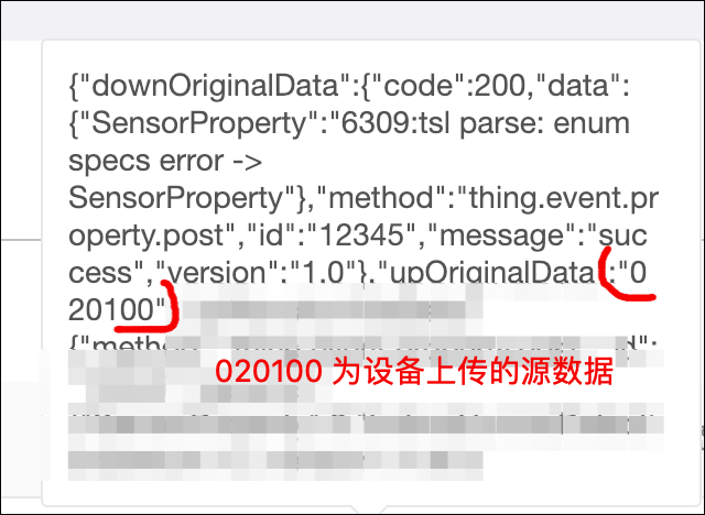
The data logs received from the device indicate that all communication links are working as expected. The following figure shows a raw uplink log.
Step 5: Parse the data uploaded by the device
The sensor reports data in binary format. You must parse the binary data to convert it into human-readable property names. To do this, perform the following steps.
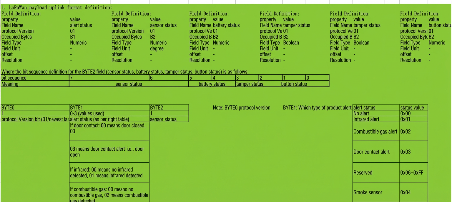
The following figure shows the binary configuration file provided by the manufacturer.
Define the Thing Specification Language model.
For this sensor model, in the binary sequence
020100, the first byte02indicates the protocol version. The value01indicates that the infrared sensor detects occupancy, and00indicates that the sensor status is normal. You must first define two features for the product: Indoor Human Detection Switch and Sensor Property. These features are used to record the two properties.In the IoT Platform console, choose Device Management > Products in the navigation pane on the left. Click View next to the product to go to the product details page.
Click the Feature Definition tab, and then click Edit Draft > Add Custom Feature.
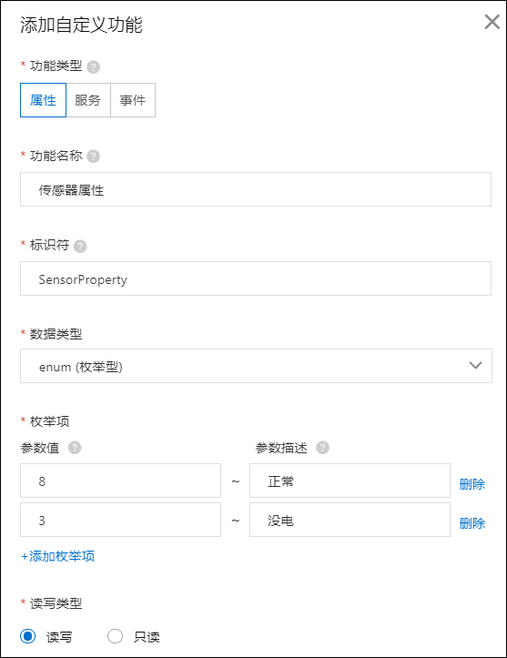
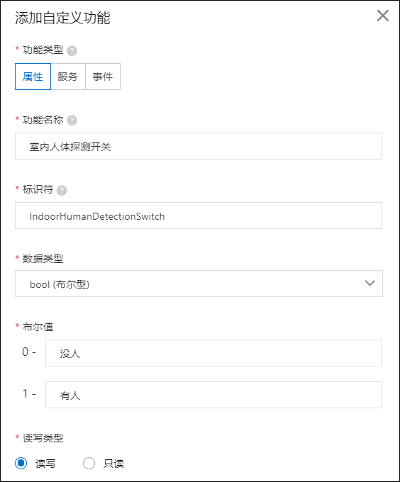
In the Add Custom Feature dialog box, set Feature Type to Property and add the following two properties.
Add Sensor Property

Add Indoor Human Detection Switch
After you add the properties, the page appears as shown in the following figure.
NoteSet the read/write type to read/write for both properties.
Use the data parsing feature in the product definition to automatically convert the binary data into the ALink-JSON format. This format is used for the two properties that you defined in the Define the Thing Specification Language model step.
NoteData parsing requires the product to be in the development status. If the product is already published, click Revoke Publication in the upper-right corner.
For more information about data conversion rules, see Data parsing. This topic provides only the final code.
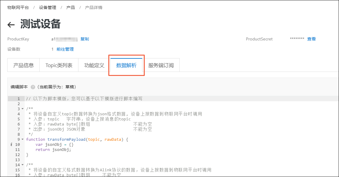
On the Product Details page, click the Data Parsing tab.
Under Edit Script, enter the following parsing script and click Save at the bottom of the page.
var COMMAND_REPORT = 02;
var COMMAND_SET = 01;
var ALINK_PROP_REPORT_METHOD = 'thing.event.property.post'; // Standard ALink JSON topic for devices to upload property data to the cloud
var ALINK_PROP_SET_METHOD = 'thing.service.property.set';
function rawDataToProtocol(bytes) {
    var uint8Array = new Uint8Array(bytes.length);
    for (var i = 0; i < bytes.length; i++) {
        uint8Array[i] = bytes[i] & 0xff;
    }
    var dataView = new DataView(uint8Array.buffer, 0);
    var jsonMap = new Object();
    var fHead = uint8Array[0]; // The 0th byte indicates the reporting protocol
    if (fHead == COMMAND_REPORT) {
        jsonMap['method'] = ALINK_PROP_REPORT_METHOD; // ALink JSON - property reporting topic
        jsonMap['version'] = '1.0'; // ALink JSON - fixed protocol version
        jsonMap['id'] = '' + 12345; // ALink JSON - request ID
        var params = {};
        params['IndoorHumanDetectionSwitch'] = uint8Array[1]; // The 1st byte indicates occupancy detected by the sensor
        params['SensorProperty'] = uint8Array[2]; // The 2nd byte indicates the sensor's own status, corresponding to the prop_float property in the product
        jsonMap['params'] = params; // ALink JSON - standard params field
    }
    return jsonMap;
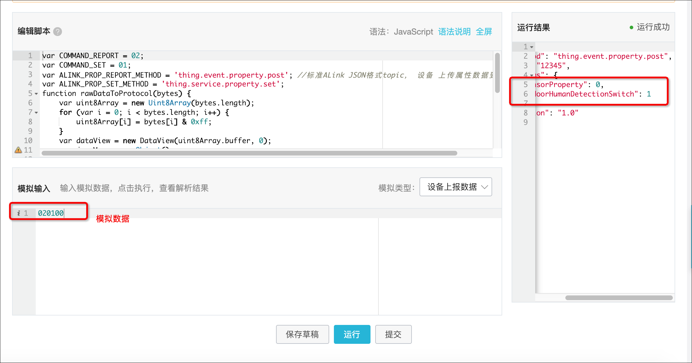
Enter the raw data 020100 for debugging. If the data is parsed successfully, as shown on the right side of the page, click Execute at the bottom of the page to run the script.
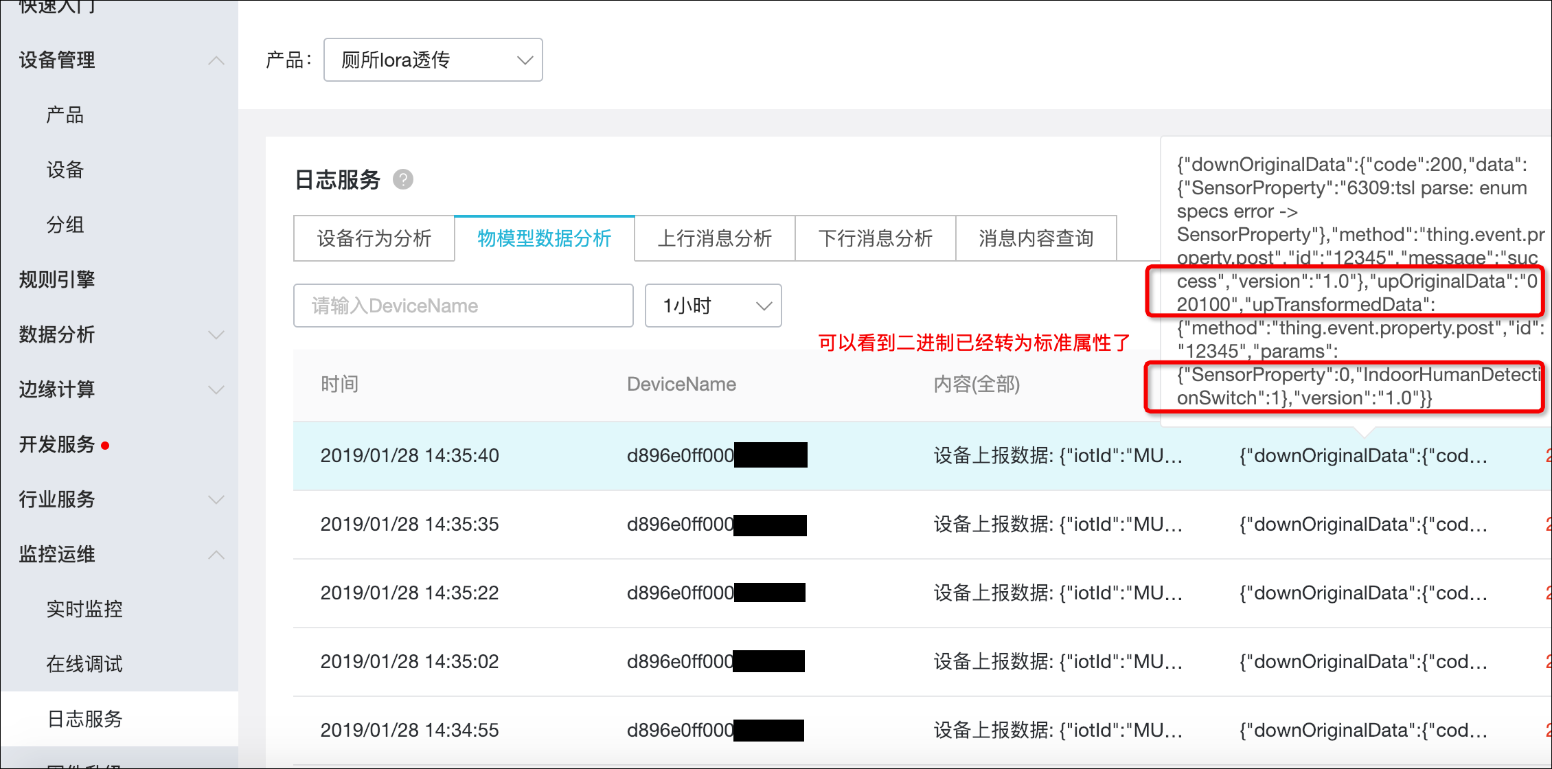
In the logs, you can see that the binary data 020100 is converted to{"SensorProperty":0,"IndoorHumanDetectionSwitch":1}. This indicates that the device is successfully integrated.
Step 6: Configure the smart toilet dashboard in IoT Studio
IoT Studio is a productivity tool that is provided by Alibaba Cloud for IoT scenarios. It covers core IoT use cases and helps solve common challenges, such as long development cycles, complex technology stacks, high collaboration costs, and difficult solution migration.
Log on to the IoT Application Development console.
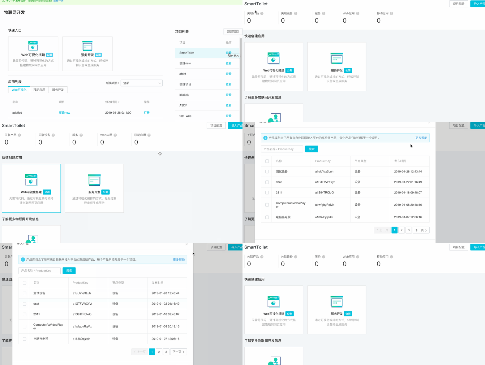
Create a new project in IoT Studio to manage the LoRaWAN smart toilet application at the project level.
After you create the project, a new item named SmartToilet appears in the right-side panel. Click View to go to the project details page. On the project overview page, click Import Product in the upper-right corner to import the product that you created.
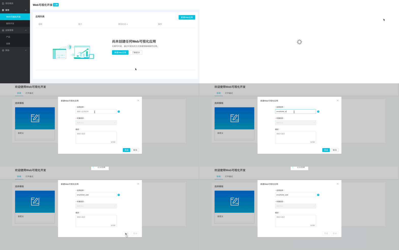
In the left-side panel, choose Recommended Web Visual Development and click Create Application to open the Web visual development workspace. Select a blank template to create a new application.
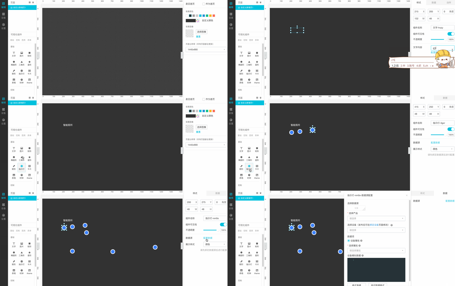
In the editor, you can change the background color and add a title. To show the stall occupancy status, you can use LED indicators that are labeled "Occupied" and "Vacant". Drag an LED indicator component onto the canvas and configure its data source.
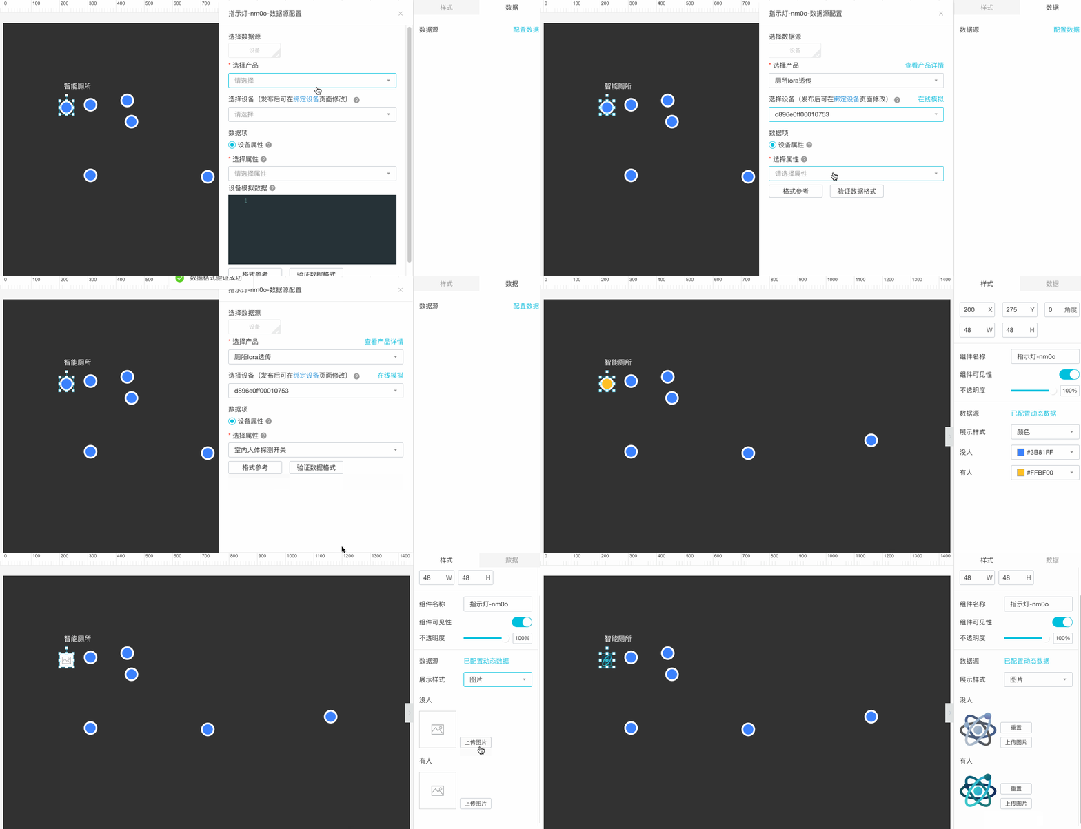
When you configure the data source, select the product, the associated device, and the Boolean property. Click Validate Data Format to verify the configuration, and then click Confirm. After the configuration is complete, you can customize the appearance of the LED indicator by uploading images for its on and off states.
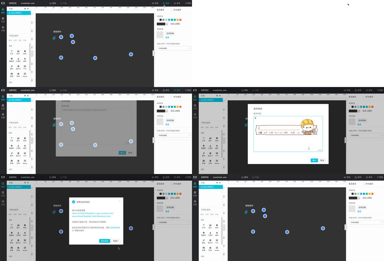
Click Preview to complete the end-to-end debugging of the web application.
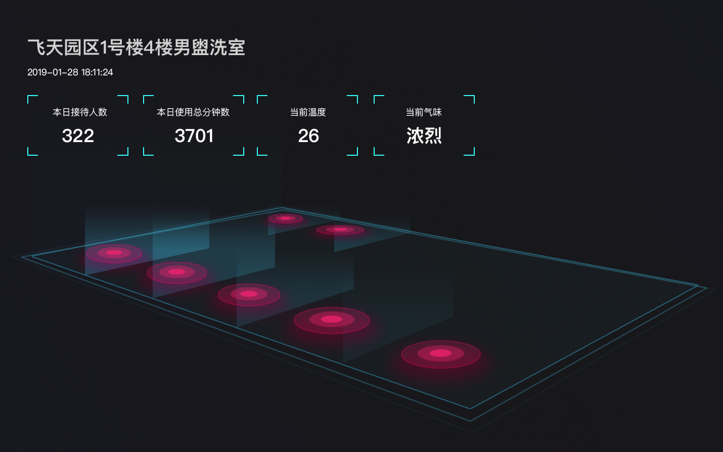
To configure seven stalls, repeat the preceding steps. You can use an Excel file to add the devices in a batch. The configuration steps for the graphical user interface (GUI) are the same and are not described here. The final result is shown in the following figure.
(Optional) Configure smart toilet status push and data dump in IoT Studio
Service Development, formerly known as Service Orchestration, lets you quickly design business logic using a visual drag-and-drop interface. It supports features such as device interaction, a WYSIWYG designer for field dependencies, service connections, API generation, data processing and dump, and backend service generation for applications. In this tutorial, you can use Service Development to push the status of smart toilet stalls and dump usage data to Tablestore.
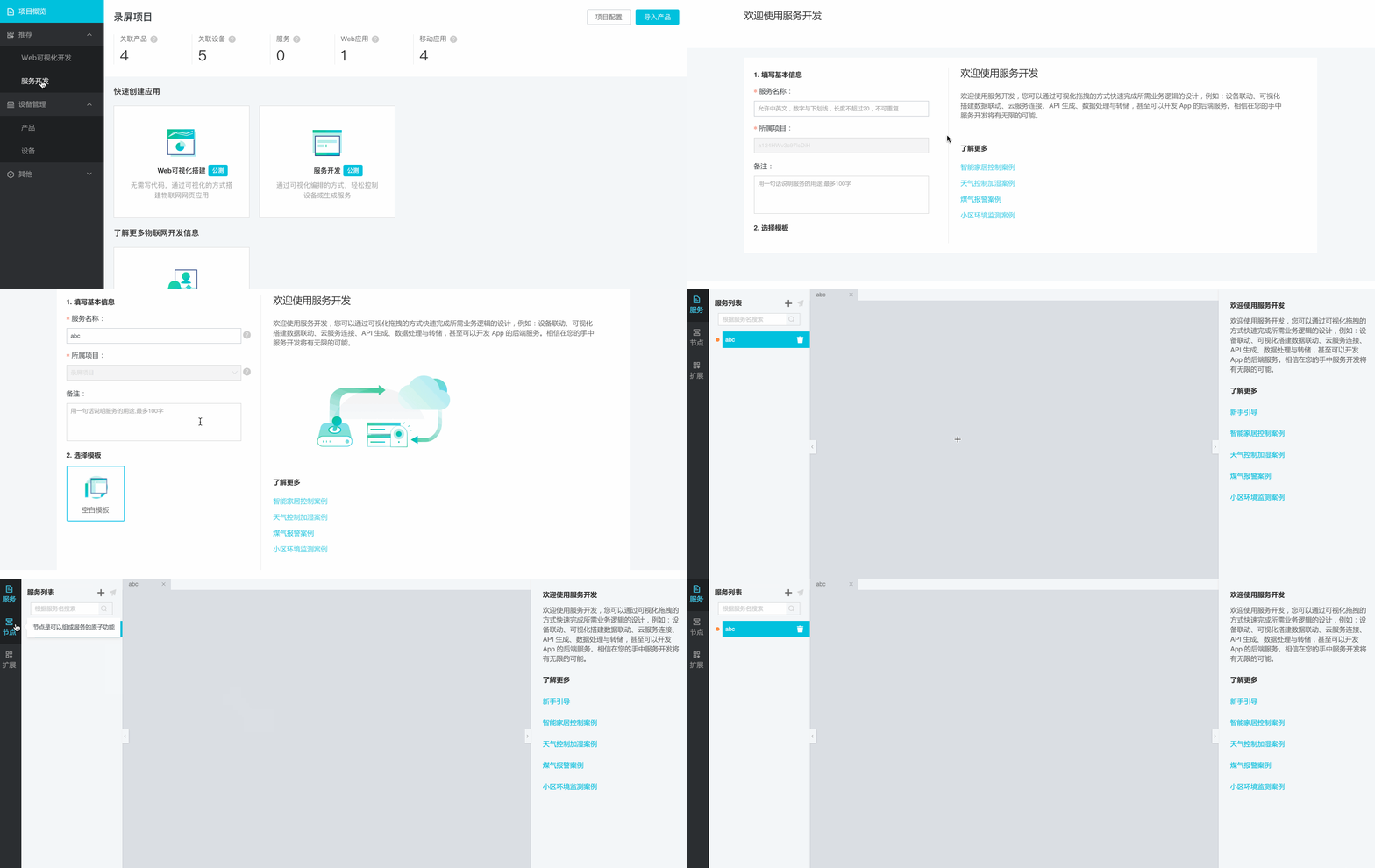
Create a new service in IoT Studio.
On the project overview page, choose Recommended Service Development and click Create Service to open the Service Development workspace. Select a blank template to create a new service.
Push the stall occupancy duration to a DingTalk Robot.
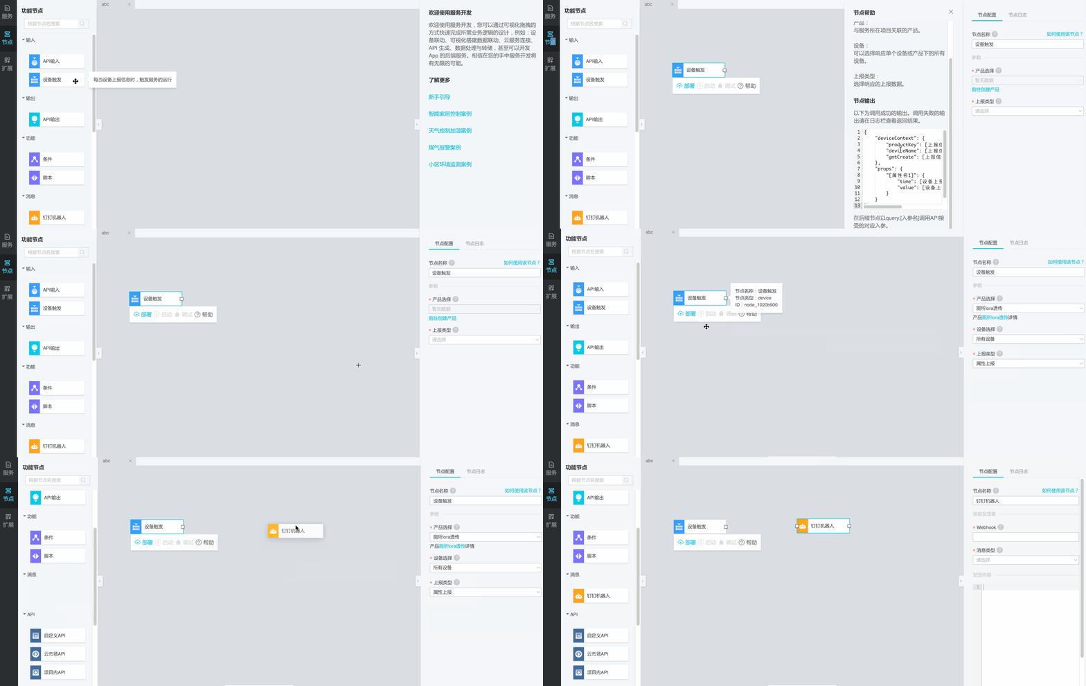
First, configure a Device Trigger node as the input. Select the product that you created. Set Device Selection to All Devices to monitor data from all devices under the product. Set Reporting Type to Property Reporting. Finally, configure a DingTalk Robot node as the message push node.
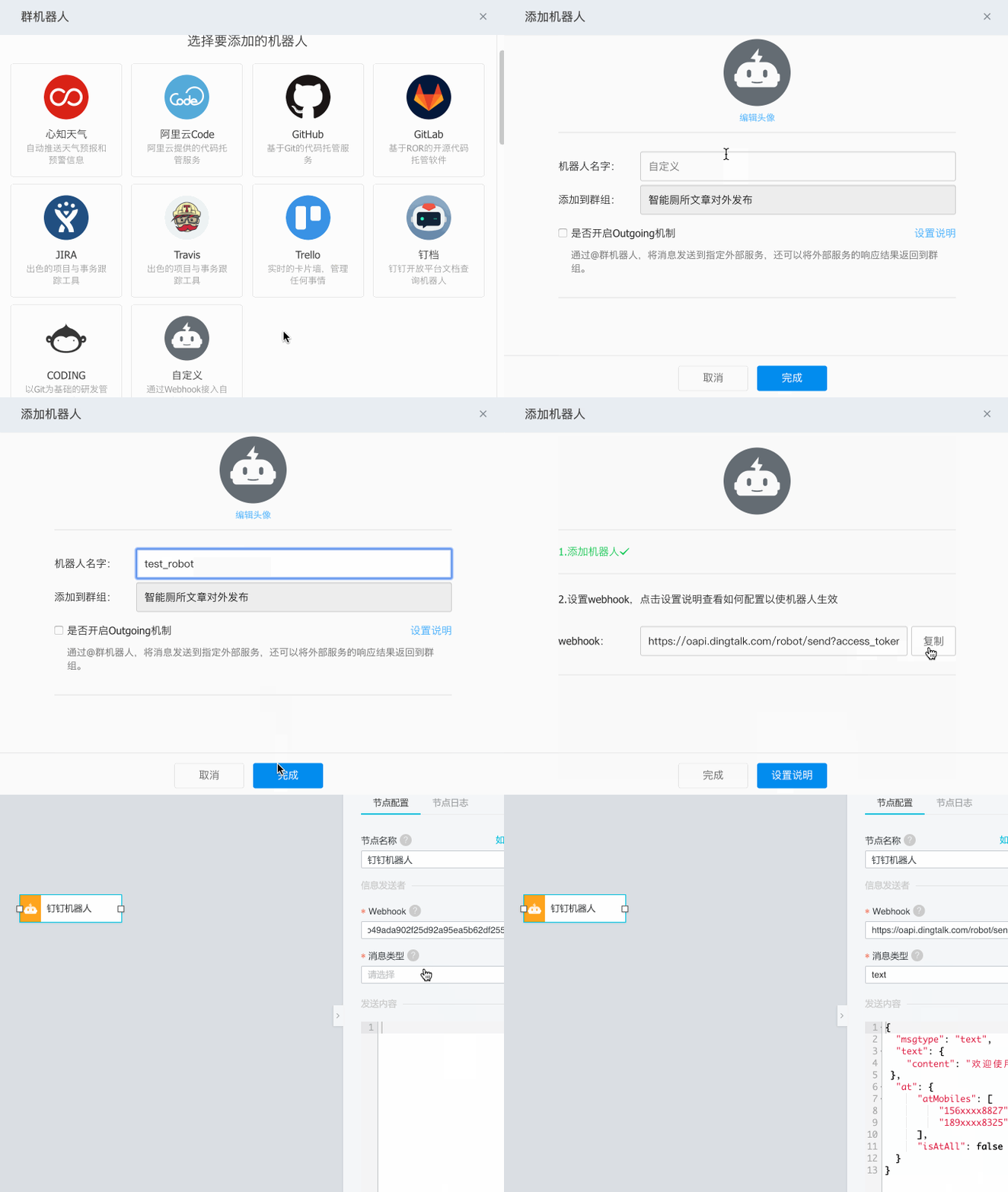
Add a robot to your DingTalk group and obtain the webhook, as shown in the following figure.
After you configure the webhook, set the content of the push message. The DingTalk Robot node supports multiple message types and dynamic device data calls.
Configure the following content in the input box:
{
  "msgtype": "text",
  "text": {
    "content":"At {{query.props.IndoorHumanDetectionSwitch.time}}, {{query.props.IndoorHumanDetectionSwitch.value}} person entered a stall!"
 },
  "at": {
      "isAtAll": true
  }
}
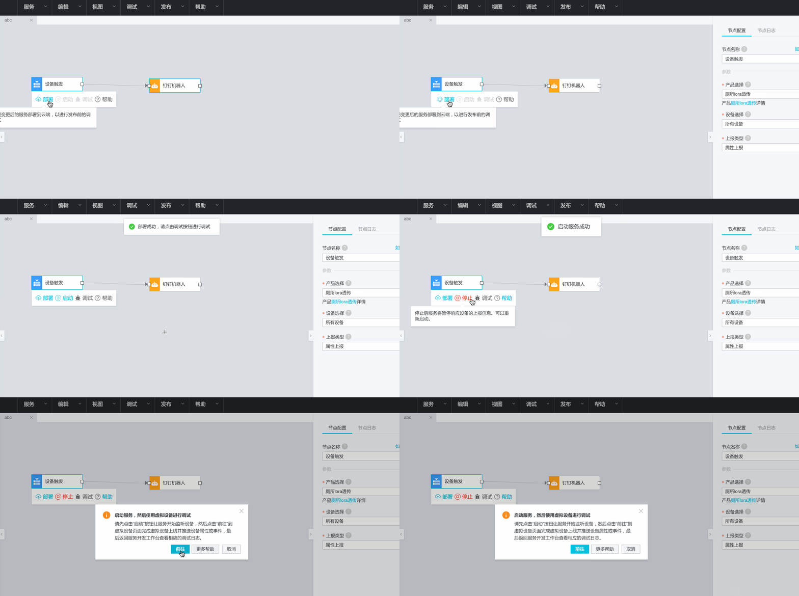
After you complete the configuration, click Deploy to deploy the service. Then, click Start to start the service.
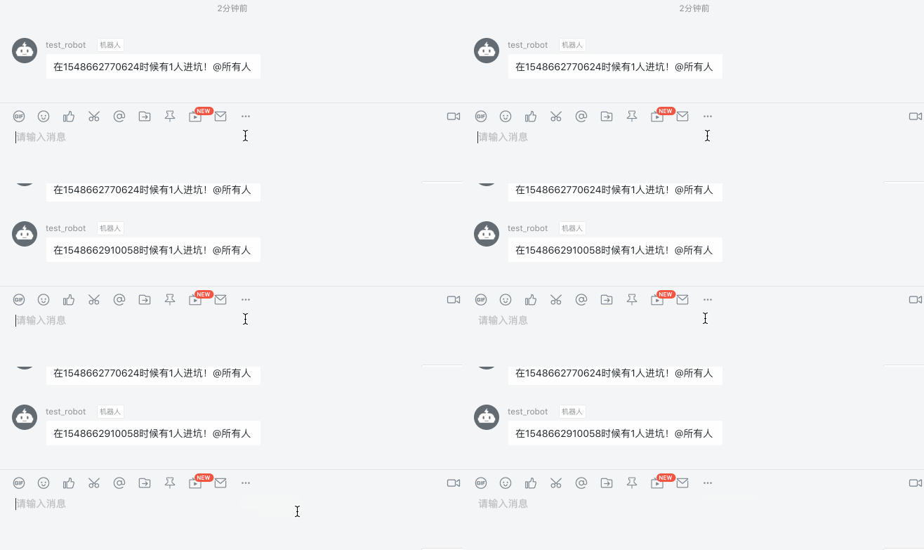
If the device is online, the robot immediately pushes messages to provide real-time updates on the stall status, as shown in the following figure.
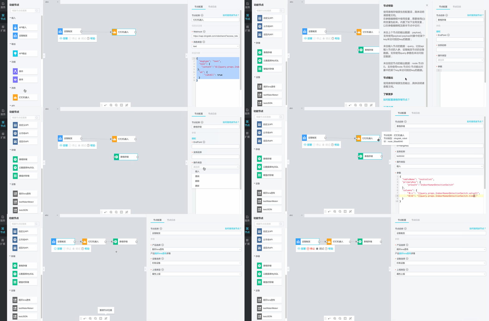
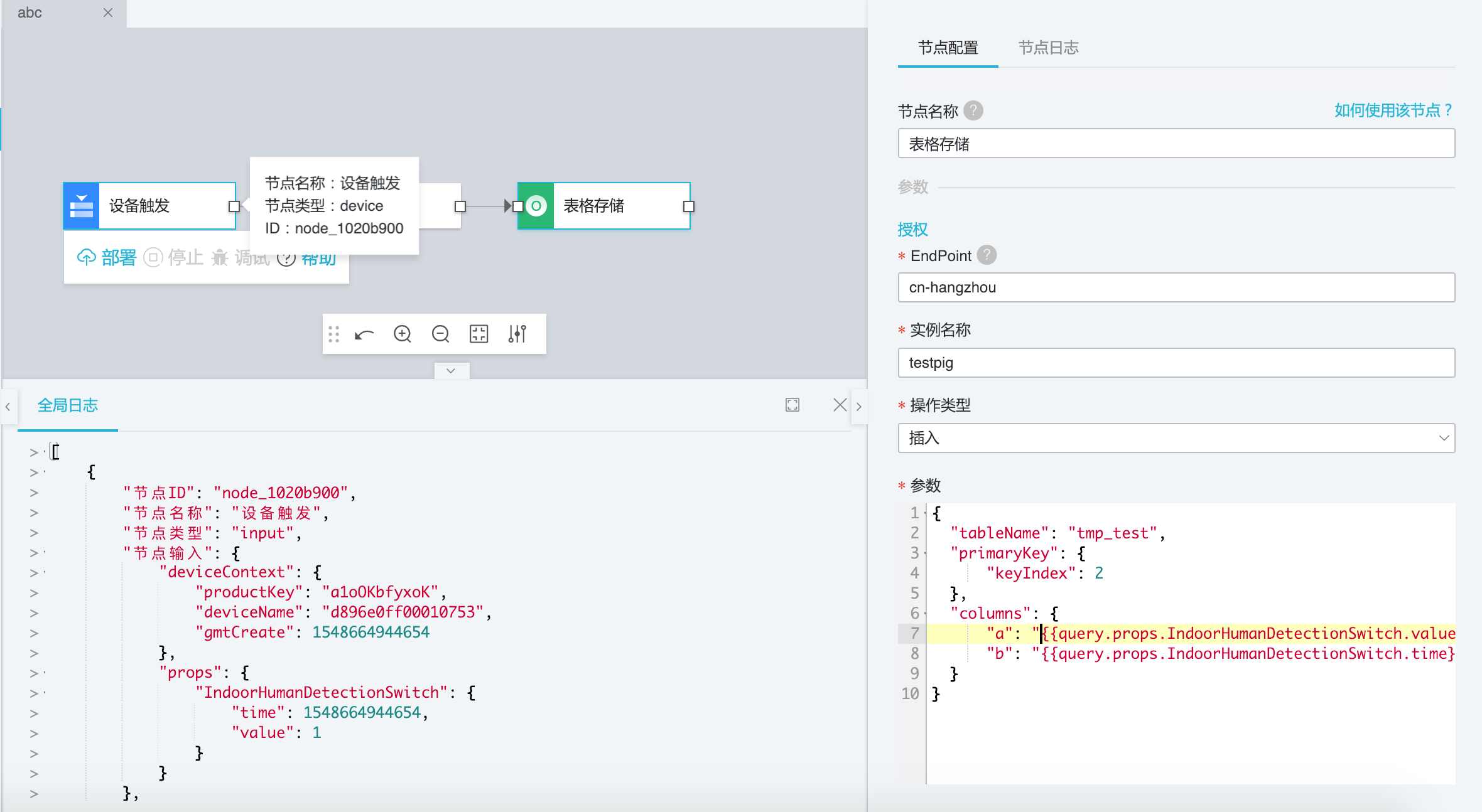
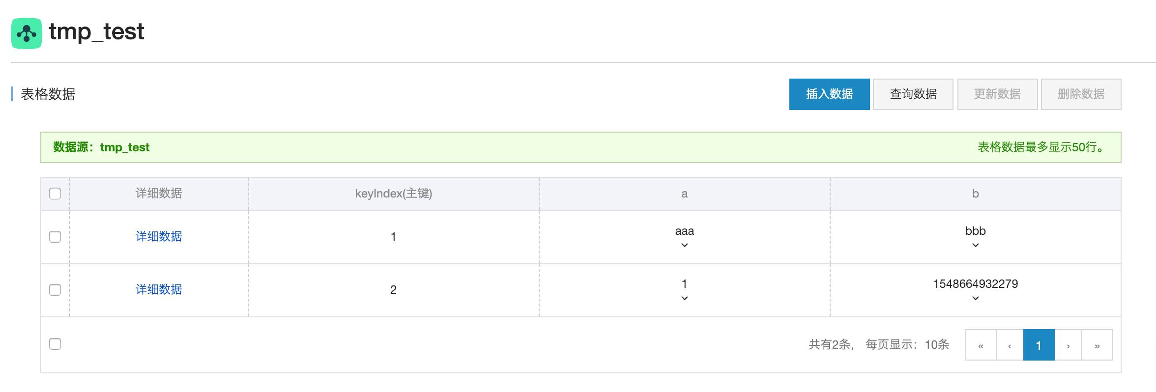
To store toilet usage data in cloud services, such as Tablestore or ApsaraDB for MySQL, you can use a storage node.
Final result: