This topic describes how to quickly set up a dedicated Link WAN network after you purchase a Link WAN Enterprise instance.
Background information
You can obtain a gateway in one of the following two ways:
Port the Alibaba Cloud Link WAN gateway SDK, version 2.5.0 or later. You must purchase and install a Link WAN key to use the gateway.
NoteFor more information about porting the gateway SDK and purchasing a Link WAN key, see Gateway SDK.
Browse the AIoT Device Center and select a recommended gateway hardware. The hardware must be compatible with Alibaba Cloud Link WAN gateway SDK 2.5.0 or later.
You can obtain a node module in one of the following two ways:
Port the Alibaba Cloud Link WAN node SDK. You can purchase a Link WAN key or issue a custom key. You must install the key to use the node module.
NoteFor more information about porting the node SDK and purchasing a Link WAN key, see Node SDK.
Browse the AIoT Device Center and select a recommended node module.
If you purchase a device with a pre-installed key, check for the following information when you receive it:
Gateway device information: GwEUI and PIN Code.
Node device information: DevEUI, PIN Code, JoinEUI, and AppKEY.
Step 1: Go to the enterprise instance
Log on to the IoT Platform console.
On the Instance Overview page, click the Link WAN Enterprise instance that you purchased.
Step 2: Add a gateway
In the navigation pane on the left, choose Link WAN > Gateway Management.
On the Gateway List tab, click Add Gateway.
On the Add Gateway page, configure the gateway information and click OK.
Parameter
Description
Basic information
Name
Enter a name for the gateway. The name can contain Chinese characters, letters, digits, and underscores (_). It must be 4 to 30 characters in length. A Chinese character is counted as two characters.
GwEUI
The GwEUI of the gateway. It is a 16-digit hexadecimal value. This value is usually on the gateway label.
PIN Code
The PIN Code. It is a 6-digit number. This value is usually on the gateway label.
Frequency Band
Select one of the following frequency bands:
CN470 Fixed-frequency
CN470 Frequency Hopping
AS923 Fixed-frequency
The example in this topic uses CN470 Non-Hybrid.
Communication Mode
The communication mode can be Full-duplex or Half-duplex. This topic uses Half-duplex as an example.
Gateway Description
Enter a description for the gateway. The description can be up to 100 characters in length. This parameter is optional.
Location information
Region
Select the region where the gateway is located.
Location Details
Enter the specific location of the gateway, or click a location on the map to the right.
After you add the gateway, power it on and make sure it is connected to the Internet through a 4G or Ethernet connection.
You can view the status of the gateway on the Gateway Management page. A status of Online indicates that the gateway is in service and you can manage the network. The following figure shows an example.
Step 3: Add a join permission
In the navigation pane on the left, choose Link WAN > Join Permissions.
On the Join Permissions page, click Add Join Permission.
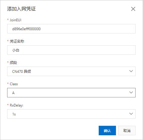
In the Add Join Permission dialog box, configure the parameters and click OK to create the permission.
Parameter
Description
JoinEUI
The application EUI. It is a 16-digit hexadecimal value. The default value is d896e0efff000000. This value can be changed.
Credential Name
Enter a name for the permission. The name can contain Chinese characters, letters, digits, and underscores (_). It must be 4 to 30 characters in length. A Chinese character is counted as two characters.
Frequency Band
Select one of the following frequency bands:
CN470 Fixed-frequency
CN470 Alternate Frequency
AS923 Fixed-frequency
This topic provides an example using CN470 Different Frequency.
Class
The following options are available:
A
B
C
D2D
This topic uses A as an example.
RxDelay
This parameter is available when you select Class A.
It specifies the delay before the receive window opens after an uplink transmission. Default value: 1 s. Valid values: 1 s to 15 s.
Step 4: Create a product and define its TSL model
In the navigation pane on the left, choose Device Management > Products, and click Create Product.
On the Create Product page, configure the parameters and click OK.
In this example, the parameters are set as follows. Use the default values for other parameters.
Parameter
Description
Product Name
Test--Temp&Humi. This is a custom name.
Category
Select Custom Category.
Node Type
Select Directly Connected Device.
Connection Method
Select LoRaWAN.
Join Permission
Select a permission from the list or click Create Permission.
Data Format
Select Pass-through/Custom.
Authentication Method
Select Device Secret.
Add a Thing Specification Language (TSL) model to define product features.
In the navigation pane on the left, choose Device Management > Products. Find the product and click View in the Actions column.
On the Product Details page, click the Features tab and then click Edit Draft.
Define the product's TSL model by adding properties, events, and services. You can add TSL models individually or in batches. All devices that are imported under this product inherit this model. For more information, see TSL model.
Create a data parsing script.
The data format for communication between LoRaWAN devices and IoT Platform is Pass-through/Custom. Therefore, you must use a data parsing script to parse uplink and downlink data. For more information, see Parse data from LoRaWAN devices.
Step 5: Add a device
In the navigation pane on the left, choose Device Management > Devices.
On the Devices page, click Add Device.
In the Add Device dialog box, enter the device information and click OK.
Parameter
Description
Product
Select a product. The new device inherits the features and attributes defined for the product.
DeviceName
Set a name for the device. The name can contain letters, digits, hyphens (-), underscores (_), at signs (@), periods (.), and colons (:). It must be 4 to 32 characters in length.
NoteThe DeviceName can be left empty. If it is empty, IoT Platform generates an identifier to use as the DeviceName.
Nickname
Set a nickname for the device. The nickname can contain Chinese characters, letters, Japanese characters, digits, and underscores (_). It must be 4 to 64 characters in length. A Chinese or Japanese character is counted as two characters.
Step 6: View uplink and downlink data
In the navigation pane on the left, choose Link WAN > Node Groups.
Find the node group and click View in the Actions column to view the device authentication information.
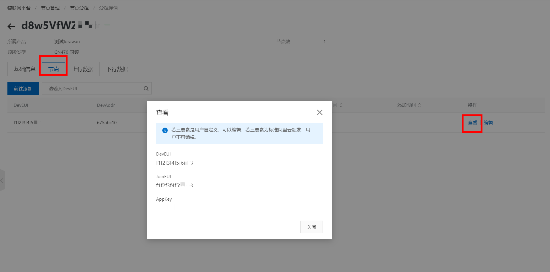 Note
NoteIf you use a custom key, you can edit it. After you edit the key, you must flash the new device authentication information to the device and trigger the join process again. The device can communicate properly only after it successfully joins the network.
On the Group Details page, click the Uplink Data or Downlink Data tab to view the uplink and downlink data of the LoRaWAN link layer communication.
Step 7: Configure the rules engine
Link WAN data forwarding in an Enterprise instance uses the IoT Platform rules engine.
The IoT Platform rules engine includes the following features:
Server-side subscription: You can subscribe to one or more types of messages from all devices under a product. Your server can use an AMQP client or a Simple Message Queue (formerly MNS) client to receive the subscribed messages.
Data forwarding: Based on the data forwarding rules that you configure, IoT Platform forwards specified fields from messages of a specified topic to a destination for storage and processing.