Tracing analysis
Analyze full trace data in real time by combining filter conditions and aggregation dimensions to diagnose performance issues across various scenarios.
Try the feature
Alibaba Cloud Playground provides a demo environment where you can experience the main features of Cloud Monitor 2.0.
-
Go to the Playground Demo. The workspace page is displayed by default.
-
In the navigation pane on the left, choose .
Filter traces
Log on to the Cloud Monitor 2.0 console, and select a workspace. In the left navigation pane, choose .
-
In the top navigation bar, click Tracing Analysis. Then, in the upper-right corner of the page, set the time range for the query.
-
Filter the traces.
-
In the Quick Filter area on the left, you can filter traces by status, latency, application name, API name, and host address.
The filter conditions appear in the text box at the top of the page.
-
Click the text box at the top. In the drop-down window, you can modify the filter conditions or set filter conditions for other dimensions.
-
You can also enter query conditions directly in the text box at the top. For more information about the query syntax, see Query syntax for Tracing Analysis.
Note-
Select an aggregation dimension to aggregate the filtered data by that dimension.
-
Click the
 icon to the right of the text box to save the current filter conditions.
-
Click Saved Views to the right of the text box to view your saved filter conditions. Click a filter condition to view the matching trace information.
-
-
Trace list
After you configure the filters, the Tracing Analysis page displays the query results, including a column chart of calls and HTTP errors, a time-series curve of call latency, and the Span List and Trace List.
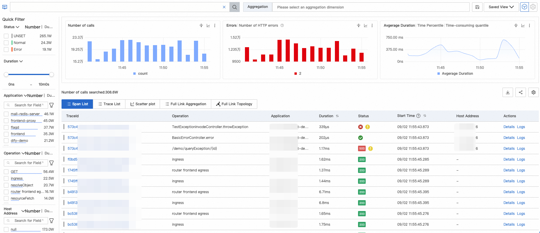
Legend:
-
HTTP status codes in the bar chart in the upper part of the page:
-
2XX (green)
-
3XX (yellow)
-
4XX (orange)
-
5XX (red)
Derived from the
attributes.http.status_codeorattributes.http.response.status_codefield. HTTP status codes override span states when both fields exist. -
-
Color bars on the left of the TraceId column of the list:
-
 :
statusCode=0 -
 :
statusCode=1 -
 :
statusCode=2
-
-
Span state indicators in the Status column of the list:
-
 : normal
-
statusCode=0(unconfigured) -
statusCode=1(normal)
-
-
: error (
statusCode=2) -
: exception (triggered when
attributes.excep.idscontains a value)
-
 : normal
 : error (
 : exception (triggered when
In the Span List and Trace List areas, you can perform the following operations:
-
Click the TraceId of the target trace, or click Details in the Actions column to view the trace details and topology view. For more information, see Trace details.
-
Click Logs in the Actions column for the target trace to view its logs. For more information, see Log Analysis.
-
In the Trace List, the root span is displayed for each TraceId by default. Click the
icon to expand the trace and view all its spans. -
Click the
icon in the upper-right corner to add or hide parameters in the list. -
Hover over a trace parameter and click the
icon on the right to add the current parameter value as a filter condition.
 icon to expand the trace and view all its spans.
 icon in the upper-right corner to add or hide parameters in the list.
 icon on the right to add the current parameter value as a filter condition.
Scatter chart
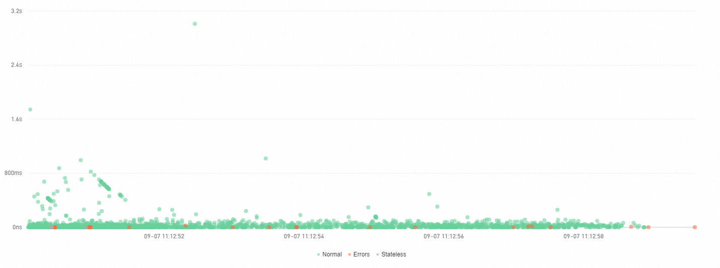
The Scatter Chart page displays the latency distribution of traces. The horizontal axis represents time and the vertical axis represents latency. Hover over a point to view the basic information of the corresponding trace, or click a point to view its call details.
Full-trace aggregation
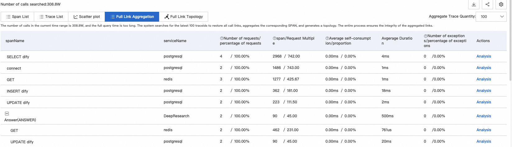
Tracing Analysis can analyze queried spans across various dimensions but targets individual spans without in-depth trace-level analysis. Full-trace aggregation queries up to 5,000 TraceIDs based on specified conditions, retrieves the corresponding spans, and aggregates them to ensure trace integrity.
Full-trace aggregation calculates data based on your query conditions. Selecting many conditions may increase query latency.
|
Parameter |
Description |
|
spanName |
The name of the span. |
|
serviceName |
The name of the application to which the span belongs. |
|
Number of requests/Request ratio |
The percentage of requests that call this span node. For example, 10% means that 10% of requests call this span. Formula: Request ratio = (Number of requests for the current span / Total number of requests) × 100% |
|
Number of spans/Request multiplier |
The average number of times this span is called per request. For example, 1.5 means that each request calls this span 1.5 times on average. Formula: Request multiplier = Number of spans / Number of requests for the span |
|
Average self-duration/Ratio |
The average self-duration excludes the duration of child spans. For example, for Span A and its child Span B, if the duration of A is 10 ms and the duration of B is 8 ms, the self-duration of A is 2 ms. Formula: Self-duration = Span duration - Total duration of all child spans Important
For an asynchronous invocation, the self-duration is the same as the span duration. You do not need to subtract the duration of child spans. |
|
Average duration |
The average duration of the span. |
|
Number of exceptions/Exception ratio |
The percentage of requests that have exceptions. For example, 3% means that 3% of requests have exceptions. Formula: Exception ratio = Number of exceptional requests / Total number of requests Important
The number of exceptional requests is not equal to the number of exceptions (the number of times a span call has an exception). When the request multiplier is greater than 1, one exceptional request may correspond to multiple exceptions. |
|
Analyze |
Adds the spanName and serviceName to the filter conditions to query the corresponding traces. |
Example: In the following table, Span A calls Span B and Span C. The parameters are described as follows.
|
spanName |
serviceName |
Number of requests/Request ratio |
Number of spans/Request multiplier |
Average self-duration/Ratio |
Average duration |
Number of exceptions/Exception ratio |
|
|
A |
- |
demo |
10/100.00% |
10/1.00 |
5.00 ms/25.00% |
20 ms |
2/20.00% |
|
- |
B |
demo |
4/40.00% |
8/2.00 |
16.00 ms/100.00% |
16 ms |
2/50.00% |
|
- |
C |
demo |
1/10.00% |
1/1.00 |
4.00 ms/100.00% |
4 ms |
1/100.00% |
For the entry span A, the Number of requests/Request ratio indicates that the total number of requests for A is 10, with a ratio of 100%. For B, the Number of requests/Request ratio is 4/40.00%, which means only 4 requests called B. Similarly, only 1 request called C. The corresponding request ratios are 40% and 10%. The remaining requests may not have called B or C because of logic checks or exceptions. This reflects the request distribution ratio.
For A, the Number of spans/Request multiplier is 10/1.00, which means each request called A only once. However, for B, 4 requests have 8 spans, meaning each request called B twice. This reflects the span distribution ratio within a single request.
For A, the Average self-duration/Ratio is 5.00 ms/25.00%. This means the average duration of A, excluding B and C, is 5 ms, which accounts for only 25% of the total average duration. For child spans B and C, their self-duration is the same as their total duration because they have no child spans. This reflects the duration distribution ratio.
For A, the Number of exceptions/Exception ratio is 2/20.00%, which means A had 2 exceptions, accounting for 20% of the total requests. For B, the Number of exceptions/Exception ratio is 2/50.00%. Because each request called B twice and the total number of requests is 4, an exception ratio of 50% means that 2 requests had exceptions. Therefore, the distribution for B might be as follows: out of 4 total requests, 2 requests had 4 normal calls to Span B. In the other 2 requests, the first call to Span B failed with an exception, and it was then successfully called again.
To view specific trace details, hover over the blue span name. In the pop-up box, you can see the recommended trace ID. Click the TraceId to view the details.
Full-trace topology
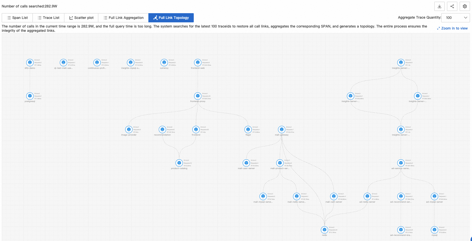
The Full-trace Topology tab displays the aggregated topology between applications, showing call relationships along with request counts, errors, and response time.
Trace details

Component labels (① in the figure)
-
The labels show the call type and the number of spans of that type in the trace.
-
The call type is distinguished by the component.name in the span attributes (attributes.component.name).
-
Click a component label to hide spans of that type in the trace. This helps you filter out spans that you do not need to focus on. Click the label again to show them.
Trace trail map (② in the figure)
The trace trail map displays the entire trace and the distribution of span data.
-
Each bar in the trace trail map represents a span. Only spans with a duration of more than 1% of the total duration are shown.
-
Different applications are distinguished by different colors. For example, in the sample figure, blue represents the opentelemetry-demo-adservice application.
-
The length of the black line in the trail map represents the self-duration of the span. This is the span duration minus the sum of the child span durations. For example, if Span A calls Span B, the duration of A is 10 ms, and the duration of B is 8 ms, then the self-duration of A is 2 ms.
-
The timeline represents the time span of the entire trace.
Trace focusing and filtering (③ in the figure)
Each row in this area represents a span and shows the parent-child hierarchy. The number before the span data indicates how many child spans the parent span has. You can perform the following operations:
-
Collapse: Click the
icon to collapse or expand span data. -
Focus: Select a target span and click the
icon. The system displays only that span and its downstream data. This focuses the view on the selected span data. -
Unfocus: Click the
icon to unfocus the span data. -
Filter: In the search box, enter information contained in the target span, such as the span name, application name, or attribute. This filters for the target span and displays the call path from the entry span to the target span. To cancel the filter, delete the content in the search box and click Search.
-
Zoom in and out: Click the
icon to zoom in on the trace and hide the trace trail map. Click the icon to restore the trace trail map.
 icon to collapse or expand span data.
 icon. The system displays only that span and its downstream data. This focuses the view on the selected span data.
 icon to unfocus the span data.
 icon to zoom in on the trace and hide the trace trail map. Click the
 icon to restore the trace trail map.
Span details (④ in the figure)
The Span details area contains detailed information about the span, along with associated metrics, logs, and exception information.
-
Additional information: Includes four types of information: Attributes, Resources, Details, and Events, grouped by type. For field descriptions, see Parameters for Tracing Analysis.
-
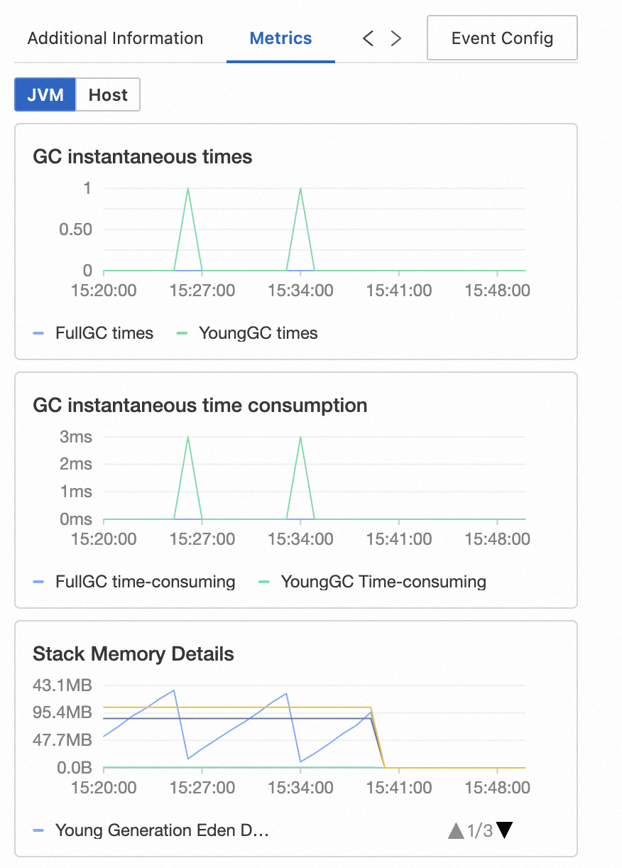
Metrics: Displays metrics associated with the span. For ARMS Java application traces, JVM and host metrics are displayed. For traces reported by open-source probes, the three RED (Rate, Errors, and Duration) metrics are displayed.
-
Log association: If you have associated a Simple Log Service Logstore with your application, you can navigate to the Logstore and query the business logs for the current TraceId.
-
Exceptions: When a span records exception information, this page displays the exception details.
-
Event configuration: Set interaction events for one or more trace attributes to query more detailed traces or view associated logs and metrics. For more information, see Configure custom interaction events for traces.
Custom development
Trace data is stored in your Simple Log Service (SLS). The Project name is proj-xtrace-<encode>-<region-id>, and the Logstore name is logstore-tracing. <region-id> is the region of Tracing Analysis, such as cn-hangzhou. For the data format, see Parameters for Tracing Analysis. You can perform custom development based on the stored full trace data by combining filter conditions and aggregation dimensions for real-time analysis. For more information, see Analyze trace data in real time.