This topic uses a dual-cluster deployment in an intra-city active-active architecture as an example to help you get started with LHC.
LHC also supports application deployment in a unitized architecture. For more information, see Overview.
In a dual-data-center scenario, maintain a 1:2 ratio of unitized workspaces to zones (data centers).
Background information
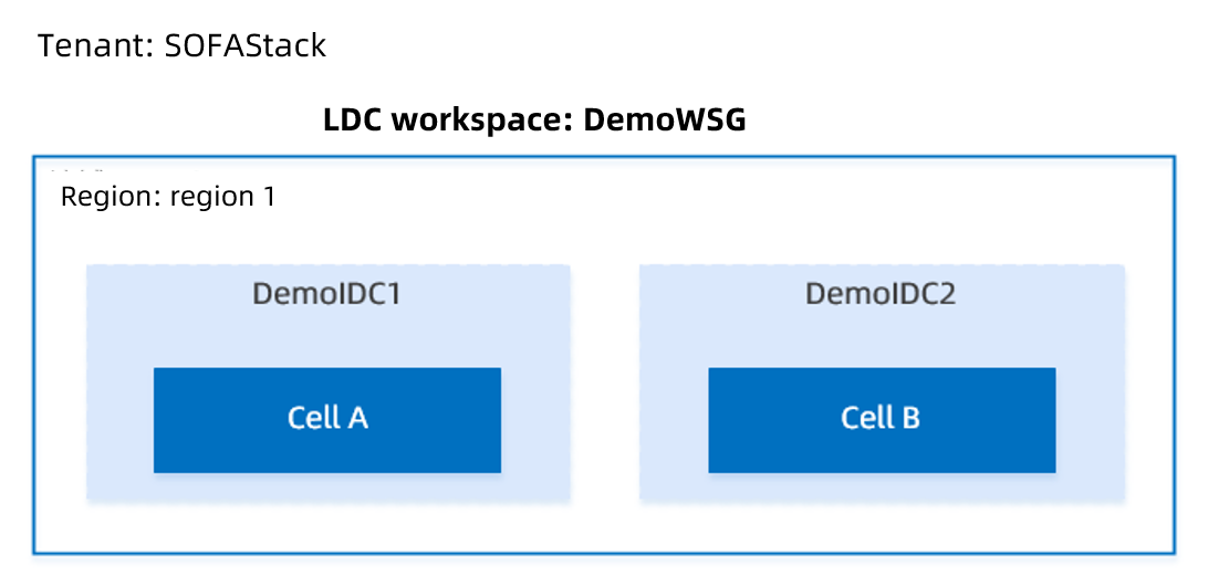
The following figure shows the deployment architecture. Under a SOFAStack tenant, you create a workspace group in a region and associate two workspaces with the group. Each workspace corresponds to a different zone (data center), and each data center corresponds to a deployment unit (Cell).
Step 1: Create a unitized workspace
In this step, you create a unitized workspace that includes two zones.
Log on to the LHC console.
In the navigation pane on the left, click Global Settings to go to the workspace list page.
Click Create Workspace, select the Unitized Workspace type, and click Create.
On the Create Workspace page, enter the following basic information.
Workspace ID: The ID must be 2 to 45 characters in length, start with a letter, and contain only letters and digits. The workspace ID must be globally unique and cannot be changed after it is created. Examples: dev, test, and prod. In this example, enter
DemoWSG.Workspace Name: The name must be 1 to 64 characters in length. This is the display name of the workspace. Examples: Development Workspace, Test Workspace, and Production Workspace. In this example, enter
DemoWSG.Region: The region where the workspace is located. A workspace must belong to a region.
Network Type: Select VPC.
Import VPC: Keep this option disabled.
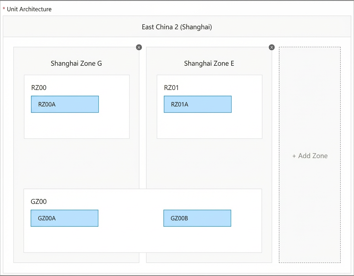
Click Next. On the Create Unitized Architecture page, click Add Zone. You can add an unlimited number of zones to each workspace. In this example, two zones are added to the workspace to prepare for architectures such as dual-data center high availability (HA).
NoteThe system automatically generates a unitized architecture topology and divides logical units and deployment units based on the zone configuration.
Click Next. On the Create VPC page, enter the following configuration information:
VPC Name: The name must be 2 to 128 characters in length. It must start with a letter or a Chinese character and can contain digits, underscores (_), and hyphens (-). You can use the automatically generated name
Unitized-Workspace-ID-vpc.VPC CIDR Block: The CIDR block of the VPC. This cannot be changed after the VPC is created. All resources in the VPC, such as Elastic Compute Service (ECS), ApsaraDB RDS (RDS), and Server Load Balancer (SLB) instances, are assigned private IP addresses from this CIDR block. The following CIDR blocks are available:
10.0.0.0/8
172.16.0.0/12
192.168.0.0/16
Description: Optional. Enter a description for the VPC. The description cannot start with
http://orhttps://.vSwitch: Click Add vSwitch. In the Create vSwitch window that appears, enter the following information and click Submit.
Name: The name of the vSwitch. The name must be 2 to 128 characters in length. It must start with a letter or a Chinese character and can contain digits, underscores (_), and hyphens (-). The system automatically generates a default name in the format
Unitized-Workspace-ID-vsw.Zone: The zone of the vSwitch. vSwitches in different zones within the same VPC can communicate with each other over the internal network. You must create a vSwitch for each zone.
Custom CIDR Block: Disabled by default. If you enable this option, you must specify a CIDR block.
Subnet Mask: If Custom CIDR Block is disabled, you must select a subnet mask and a CIDR block. The default subnet mask for a VPC is /24, such as 172.31.0.0/24. The value can range from /16 to /29, which provides up to 65,532 addresses.
Description: Enter a description for the vSwitch. The description must be 2 to 256 characters in length and cannot start with
http://orhttps://.
Click Next. On the Create Security Group page, click Add Security Group. In the Add Security Group window that appears, enter the following information and click OK.
Security Group Name: The name must be 2 to 128 characters in length and start with a letter. It can contain letters, digits, hyphens (-), and periods (.). The system automatically generates a default name in the format
Unitized-Workspace-ID-sg.Description: The description must be 2 to 256 characters in length and cannot start with
http://orhttps://.Rules: Keep the default settings to allow all inbound and outbound traffic.
Click OK to return to the Create Security Group page, and then click Submit.
Step 2: Create a cluster
A cluster is a logical group for running workloads. It contains a group of Elastic Compute Service (ECS) resources, and each ECS instance is a node in the cluster. When you use LHC for the first time, you must create an initial cluster and add at least one node.
Prerequisites
You have administrative permissions for LHC.
You have created a unitized workspace.
Before you use a Container Service for Kubernetes (ACK) cluster for the first time, you must grant ACK permissions to access cloud resources. For more information, see Authorize ACK to access cloud resources.
In this example, you create a cluster for each of the two zones: democluster1 and democluster2. This implements an intra-city active-active architecture.
You cannot create multiple clusters in the same zone. If the current zone or vSwitch already has a cluster, go to the Workspace Management page to add a new zone and vSwitch to the current workspace.
Procedure
Log on to the LHC console. In the navigation pane on the left, click Cluster Management > Cluster Details.
On the cluster list page, click Create Cluster.
On the Create Cluster page, the system automatically runs a precheck to ensure that the required products are activated and that your account balance is greater than CNY 100. After the precheck passes, click Next.
NoteIf the precheck fails, fix the failed items and click Check Again to run the precheck again.
On the Basic Configurations page, complete the following basic cluster configurations and click Next.
Basic Information:
VPC: Kubernetes clusters support only VPCs. You can select a VPC from the list of existing VPCs.
Cluster Name: The name must be 1 to 63 characters in length and can contain digits, Chinese characters, letters, or hyphens (-). In this example, enter
democluster1anddemocluster2for the respective clusters.Kubernetes Version: Select a Kubernetes version.
1.16.9-aliyun.1and1.18.8-aliyun.1are supported. In this example, select1.18.8-aliyun.1.Container Runtime:
docker 19.03.5.
Network Configuration:
vSwitch: From the list of existing vSwitches, select the required vSwitch based on the zone. If no vSwitch is available, click Create vSwitch. For more information, see Create a vSwitch.
Network Plugin: Select a network plugin. The Terway network plugin is supported. Terway is a network plugin developed by Alibaba Cloud Container Service. It assigns elastic network interfaces (ENIs) to containers, supports Kubernetes Network Policies to define access policies between containers, and supports bandwidth throttling for individual containers. For more information, see Flannel and Terway.
Pod vSwitch: When you use the Terway network plugin, you must specify vSwitches to assign IP addresses to pods. Each Pod vSwitch corresponds to a vSwitch of a worker instance. If no vSwitch is available, click Create vSwitch. For more information, see Create a vSwitch.
Service CIDR: Set the Service CIDR block. The CIDR block cannot overlap with the VPC CIDR block or the pod CIDR block. It cannot be modified after the cluster is created. The valid ranges are 10.0.0.0/16-24, 172.16-31.0.0/16-24, and 192.168.0.0/16-24.
Advanced Configuration: Keep the default settings. For more information, see Create a professional managed Kubernetes cluster.
On the Node Configuration page, complete the following worker node configurations.
Billing Method: Pay-as-you-go and Subscription are supported. If you select Subscription, you must set the following parameters.
Duration: You can select 1, 2, 3, or 6 months, or 1 to 5 years.
Auto-renewal: Specify whether to enable auto-renewal.
Number of Nodes: The number of worker instances (ECS instances) to create.
Instance Type: You can select multiple instance types. For more information, see Instance families. You can select up to 10 instance types.
NoteYou can select multiple instance types as alternatives. When a node is created, the system attempts to purchase an instance of the first specified type. If the purchase fails, the system tries the next type until an instance is created. The final purchased instance type may vary based on inventory.
System Disk: Standard SSDs, ultra disks, and Enhanced SSDs (ESSDs) are supported.
Data Disk: Standard SSDs, ultra disks, and ESSDs are supported.
Operating System: CentOS and Alibaba Cloud Linux are supported.
Logon Password: Set the logon password for the nodes. The password must be 8 to 30 characters in length and contain at least three of the following character types: uppercase letters, lowercase letters, digits, and special characters.
Confirm Password: Confirm the logon password.
After you complete the configuration, click Next.
On the Configuration Preview page, confirm the configuration and click Submit.
NoteIt typically takes about 10 minutes to create a Kubernetes cluster with multiple nodes.
The system automatically navigates to the Create Cluster Details page. If a task fails during cluster creation, you can click the event to view the details, or click Retry or Ignore.
On the Import Cluster page, configure the following items.
Configuration item
Description
Cluster Type
Alibaba Cloud
VPC
Select the required VPC from the list of existing VPCs.
Select Existing Cluster
Select the ACK cluster to import from the list of existing clusters.
Deployment Unit
You can set different deployment units for zones.
To modify deployment units, go to Global Settings > Workspace Details.
Step 3: Create a transfer application
In the Application Management console, create an application named transfer-money.
Procedure
Log on to the Application Management console. In the navigation pane on the left, click Application List.
On the Application List page, click Create Application in the upper-right corner.
On the Create Application page, enter the following information and click Submit.
Application Name: Enter
transfer-money.NoteThe application name must be unique within the same tenant.
Technology Stack: Select SOFABoot.
Application Group: Select an existing application group. For more information, see Manage application groups.
Application Tags: Application classification tags that help you quickly retrieve applications. You can add system tags and custom tags.
Application Description: Optional. The description can be up to 500 characters in length, such as
This is a sample application. For more information, see Manage applications.
Step 4: Prepare images
LHC deploys application services using images. Before you create an application service, you must prepare an image. For your convenience, LHC provides the following publicly accessible sample images:
Image Name | Registry Address |
aks-transfermoney-server | registry-vpc.cn-shanghai.aliyuncs.com/sofa-samples/aks-transfermoney-server:20190726095608708-master.40215e87 |
aks-transfermoney-client | registry-vpc.cn-shanghai.aliyuncs.com/sofa-samples/aks-transfermoney-client:20190815134744553-master.5ea6278b |
Step 5: Create application services
Create two application services with a dependency: aks-transfermoney-server and aks-transfermoney-client.
Prerequisites
You have created a federated namespace, such as antcloud-demo. For more information, see Create a federated namespace.
Create the transfer server application service
Log on to the console. In the navigation pane on the left, click Deployment & O&M > Application Service.
On the application service list page, click Create Application Service.
On the Create Application Service page, enter the following basic information and click Next.
Namespace: Select a namespace in the cluster. The first namespace in the list is selected by default.
Application Service Name: The name of the container service. Enter
aks-transfermoney-server. The name must start with a letter, end with a letter or a digit, and can contain lowercase letters, digits, and hyphens. The name must be unique within the same namespace.Application: Select
transfer-money.Description: Optional. The description of the container service.
On the Pod Template Configuration page, enter the following information and click Next.
Container Name: Enter a name. The container name must be no more than 63 characters in length, start with a letter, end with a letter or a digit, and can contain lowercase letters, digits, and hyphens.
Access Type: Select Image Repository. Use the sample image aks-transfermoney-server. For the registry address, see Prepare images.
CPU configuration: Request cores: 200 millicores. Maximum cores: 500 cores.
Memory Configuration: Set Request Memory to 512 MiB and Limit Memory to 1 GiB.
In Advanced Configuration > Environment Variable Configuration, set
APPSVC_VERSION = V1andANTCLOUD_SOFA_PROFILE = prod.In Advanced Configuration > Health Check Configuration, set the Readiness Probe check method to
Http GET, the path to/health/readiness, and the port to8080. Configure the remaining items as prompted.Configuration Overwrite: Keep this option disabled.
On the Scaling Configuration page, enter the following information and click Next.
Replica Scaling Policy: Currently, only Fixed Replicas is supported. The default value is 0. Select the deployment units (
RZ01AandRZ02A) and change the desired number of replicas to 1. This ensures that the application service maintains a fixed number of pod replicas at runtime.On the Access Configuration page, enter the following information and click Next.
On the Access Configuration page, click Add Load Balancer.
In the Server Load Balancer window, enter the following information and click OK.
Load Balancer Name: Enter a service name. The system generates a default service name prefix of
Application-Service-Name-.NoteRecord this service name. You will need to configure it as an environment variable in the client application.
Access Method: Select Internal Network. This creates an internal service and forwards traffic to the corresponding container port.
Port Mapping: Click Add Port Mapping and enter the following information. Keep the default settings for other parameters.
Protocol: Select TCP.
Forwarding Rule: Select Round-robin.
Frontend Port: The port that the workload program in the container image listens on. Enter
80.Backend Port: The container port that is mapped to the cluster's virtual IP address. Enter
8341.
On the Deployment and Scheduling Configuration page, keep the default configurations for the application service and click Next.
On the Preview page of the application service, confirm the information and click Submit.
NoteAfter you finish editing and submit the application service configuration, add a version remark to distinguish between versions.
Create the transfer client application service
Log on to the console. In the navigation pane on the left, click Deployment & O&M > Application Service.
On the application service list page, click Create Application Service.
On the Create Application Service page, enter the following basic information and click Next.
Namespace: Select a namespace in the cluster. The first namespace in the list is selected by default.
Application Service Name: The name of the container service. Enter
aks-transfermoney-client. The application service name must start with a letter, end with a letter or a digit, and can contain lowercase letters, digits, and hyphens. The name must be unique within the same namespace.Application: Select
transfer-money.Owner: Select the owner of this application service.
Description: Optional. The description of the container service.
On the Pod Template Configuration page, enter the following information and click Next.
Container Name: Enter a name.
Access Type: Select Image Repository. Use the sample image aks-transfermoney-client. For the registry address, see Prepare images.
CPU configuration: The CPU request is 200 millicores. The CPU limit is 500 cores.
Memory Configuration: Set Request Memory to 512 MiB and Limit Memory to 1 GiB.
In Advanced Configuration > Environment Variable Configuration, set the variable name to SERVER_TM_ADDRESS and the value to the service name of the server-side application service.
On the Scaling Configuration page, enter the following information and click Next.
Replica Scaling Policy: Currently, only Fixed Replicas is supported. The default value is 0. Select the deployment units (
RZ01AandRZ02A) and change the desired number of replicas to 1. This ensures that the application service maintains a fixed number of pod replicas at runtime. Each client can handle a maximum of 1,000 concurrent stress testing requests.On the Access Configuration page, click Add Load Balancer, enter the following information, and click Next.
In the Server Load Balancer window, enter the following information and click OK.
Load Balancer Name: Enter a service name. The system generates a default service name prefix of
Application-Service-Name-.Access Method: Select Public Network. This creates an internal Service that forwards traffic to the corresponding port on the container.
NoteConfiguring an external service creates an Internet-facing SLB instance and forwards traffic to the corresponding container port. The access endpoint consists of the public IP address of the Internet-facing SLB instance and the specified port, for example,
10.117.117.117:80.Access Method: Select Public Network. This creates an internal Service that forwards traffic to the corresponding container port.
Port Mapping: Click Add Port Mapping and enter the following information. Keep the default settings for other parameters.
Protocol: Select TCP.
Forwarding Rule: Select Round-robin.
Frontend Port: The port that the workload program in the container image listens on. Enter
80.Backend Port: The container port that is mapped to the cluster's virtual IP address. Enter
8341.
On the Deployment and Scheduling Configuration page, keep the default configurations for the application service and click Next.
On the application service Preview page, confirm the information and click Submit.
NoteAfter you submit the configuration, add a version note to distinguish between versions.
On the Deployment and Scheduling Configuration page, accept the default configurations for the application service and click Next.
On the application service's Preview page, confirm the information and click Submit.
NoteAfter you edit and submit the application service configuration, add a version remark to easily distinguish between versions.
Step 6: Create a deployment order
Use a deployment order to deploy the two application services with a dependency that you created in the previous step.
Select the two application services for serial deployment.
Procedure
Log on to the console. In the navigation pane on the left, click Deployment & O&M > Deployment Order to go to the deployment dashboard.
On the deployment dashboard, click Create Deployment Order.
On the Create Deployment Order page, enter the following information and click Next.
Basic Information
Title: The title of the deployment. For example,
Demodeploy.Type: Only group deployment is supported.
Namespace: Select the namespace to which the application services to be deployed belong.
Application Service Deployment List: In the Available Application Services list, select the required application services: aks-transfermoney-client and aks-transfermoney-server. Click the > icon to add the application services to the Selected Application Services list.
NoteIf an application service has multiple submitted versions, you must select the version to deploy. The latest version is selected by default.
Advanced Configuration
Set Application Service Dependencies: aks-transfermoney-client depends on aks-transfermoney-server.
On the Preview page, confirm the information and click Create. The system automatically navigates to the Deployment Order Details page. Click Deploy All to start the deployment.
Step 7: Verify the result
Verify that the aks-transfermoney-client and aks-transfermoney-server application services are successfully deployed in both clusters.
Procedure
Log on to the console. In the navigation pane on the left, click Deployment & O&M > Application Service.
In the application service list, click aks-transfermoney-client and aks-transfermoney-server respectively to go to their details pages.
On the Pods tab, verify that one application container is running for each of the two application services in both deployment units.
For more information about application services, see View application service details.