Trace a target program
1. PPU activity tracing
asys can simultaneously collect trace data for both HGGC and mainstream GPUs. Use the -t option to specify which activities to trace for your application. If you do not specify any activities, asys traces hggc,hgtx,acdnn,acblas by default. The following table describes the PPU-related trace activities supported by the --trace option.
|
Trace activity |
Description |
|
hggc |
Execution time and call stack information for HGGC runtime/driver APIs. Execution time and call stack information for mainstream GPU runtime/driver APIs. PPU execution information: kernel, memcpy, and memset. Correlations between HGGC APIs and PPU execution. |
|
acdnn |
Execution time information for cuDNN APIs. |
|
acblas |
Execution time information for cuBLAS APIs. |
|
hgvideo |
Execution time of HG-Encode APIs. Execution time of HG-ACVID APIs. Execution time of HG-JPEG APIs. PPU execution information: video encoding and decoding. Correlations between video APIs and PPU execution. |
|
pccl |
Execution time for each stage of the PCCL communication process. |
You can control the scope of data collected by the hggc trace activity by using the --hggc-trace-set option to enable specific trace subsets. Specify multiple subsets by separating them with commas (,), for example: --hggc-trace-set=kernel-activity,kernel-api.
|
HGGC trace subset |
Description |
|
kernel-activity |
Collects information about kernel execution on the PPU. |
|
memory-activity |
Collects information about memory operations on the PPU. |
|
kernel-api |
Collects execution information for kernel-related APIs on the host. |
|
memory-api |
Collects execution information for memory-related APIs on the host. |
|
default-set |
The default setting. It includes all available trace subsets and other HGGC trace information. |
To selectively disable tracing for specific APIs in HGGC, you can configure the ASIGHT_HGGC_TRACE_BLACKLIST environment variable to specify the list of APIs to disable. Multiple API names are separated by a , (comma). For example: export ASIGHT_HGGC_TRACE_BLACKLIST=cudaEventQuery,cuEventQuery.
1.1 Device-side PPU activity
1.1.1 PPU activity
Required asys collection option: --trace hggc
When you open a collected report in the GUI tool, the tool displays the PPU's workload in the following hierarchy, as shown in the figure below:

For clarity, the same timeline can appear in multiple rows. For example, in the figure above, add_kernel appears not only in its own row but also in the Kernels and Stream rows.
If a context contains multiple streams, an [All Stream] row appears, which shows the summary information for all streams.
Tips:
-
If a device has only one context, the Context node is hidden, and its underlying Stream nodes are displayed instead. Similarly, if a context has only one stream, the Stream node is also hidden.
-
The displayed PPU device index is the physical index and is not affected by the
CUDA_VISIBLE_DEVICESenvironment variable. -
For HGGC stream memory write activities, only the start time is displayed, and the duration is set to 0.
The percentage value shown before a PPU node name represents the portion of time that the node occupies relative to its parent node. For a stream node, the calculation is as follows:
stream time percentage = 100.0 * stream duration / context duration
stream duration = sum of the durations of all events in the stream
context duration = sum of the durations of all events in the context
Therefore, 50.3% Stream 8 indicates that the stream's duration is 50.3% of its parent context's duration.
Tip: The percentage calculation for Kernel HGTX nodes under the Kernels row is an exception. Their percentage is calculated relative to the Stream node, not their immediate parent node.
Tip: After you apply a filter, the time percentages for PPU nodes are recalculated and re-sorted based on the filter's scope.
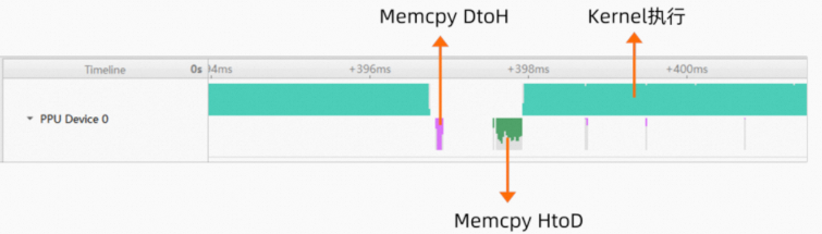
The PPU Device row summarizes the activity of the entire device. It is organized into two layers: the upper layer shows kernel execution, and the lower layer shows memory operations. Different colors distinguish memory operation types, such as HtoD, DtoH, DtoD, Pinned, and Pageable, as shown in the following figure:
1.1.2 PPU graph
Required asys collection option: --trace hggc
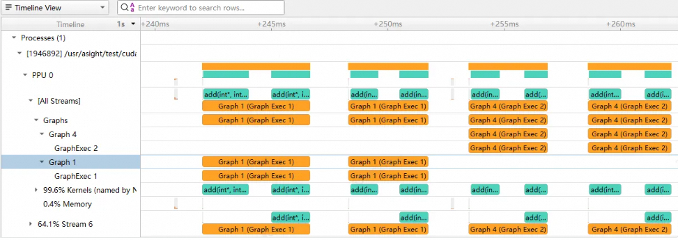
The Timeline View can display graph timelines separately to help you analyze graph execution. If a report contains graph information, graph nodes appear under the stream node in the following hierarchy:
-
Graph Group
-
Graph
-
Graph Exec
-
-
For the graph timeline, the Timeline View displays its Graph ID and Graph Exec ID, as shown in the following figure:
The device row also displays summary information for the graph.

1.1.3 PPU video
Required asys collection option: --trace hgvideo
asys can also collect PPU Video Activity data and display a corresponding timeline to help you analyze video processing performance, as shown in the following figure:
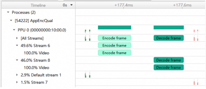
Under the stream node, a Video node displays all Video Activity for the current stream. Similar to the Kernels timeline, this information is also summarized in the PPU Device node. When you select a time range, the tooltip shows the percentage of time consumed by Video Activity, as shown in the following figure:

1.1.4 PPU HGTX projection
Required asys collection options: --trace hggc,hgtx
The Timeline View can project HGTX ranges onto each HGGC stream row under the PPU node. This projection shows the time range of PPU activities triggered within an HGTX range.

An HGTX range is projected onto the PPU based on the following correlations:
-
By correlating with HGGC APIs executed within the HGTX range. The HGTX range is projected onto the PPU activities triggered by these HGGC APIs.
-
By correlating with HGGC graph nodes created within the HGTX range (for example, creating an HGGC graph through HGGC stream capture). The HGTX range is projected onto the PPU activities corresponding to these HGGC graph nodes.
1.1.5 PPU kernel node organization
The Timeline View supports two ways to organize kernel nodes:
-
Group by kernel base name
-
Group by the kernel's HGTX
The following figure shows kernels grouped by base name:

The following figure shows kernels grouped by their associated HGTX:

You can switch between these two organization methods in the Options Dialog.

1.2 Host-side API calls
1.2.1 HGGC API
Required asys collection option: --trace hggc
Under the thread node, HGGC API calls appear. This view shows the dispatch time for HGGC kernels and the start time for memory operations.

Note: In some scenarios, return values for HGGC APIs may not be collected.
1.2.2 ACDNN
Required asys collection option: --trace acdnn
After enabling this collection, the ACDNN timeline appears under the thread node:

1.2.3 ACBLAS
Required asys collection option: --trace acblas
After enabling this collection, the ACBLAS timeline appears under the thread node:

1.2.4 Video API
Required asys collection option: --trace hgvideo
After enabling this collection, Video API calls appear, including Encode API, Decode API, and HGJPEG API calls, as shown in the following figure:

1.3 Host and device navigation
Asight Systems displays the correlation between host-side APIs and device-side activity and allows you to navigate between them.
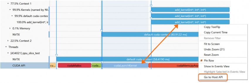
In the figure above, when you click cudaLaunchKernel, the corresponding kernel executing on the device is highlighted. Use the Go to Host API or Go to Device Activity options in the context menu to navigate between them.
1.4 HGGC Launch API and kernel name mapping
You can switch how launch API names are displayed by navigating to Tools > Options > Systems Profile > HGGC API Name Mode.
-
Display Host API name.
-
Display launched kernel name.
1.5 Dependencies between PPU activities
Kernels on different streams on the PPU can establish execution dependencies through cudaEventRecord and cudaStreamWait. The Timeline View can display these dependencies. You can display dependencies from the context menu of a PPU activity timeline or a related Event API timeline.
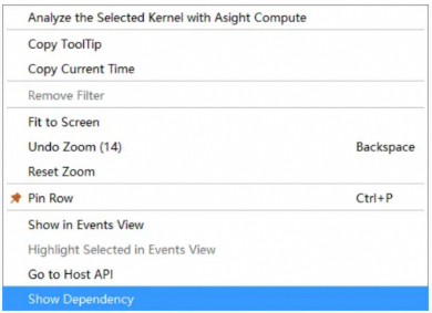
For timelines with dependencies created by event-related APIs, the Timeline View uses an orange curve to represent the dependency, as shown in the following figure:

Timelines not related to the dependency are grayed out. Hovering over the curve displays details about the dependency. After you click the curve, timelines related to this dependency path are highlighted. A green curve indicates dependencies between kernels on the same stream and dependencies on the default stream:

When an activity depends on multiple events across multiple streams, the dependencies are displayed as follows:
-
It shows the last depended-on event in the depended-on stream.
-
It does not show depended-on events that are in the same stream as the queried PPU activity.
By default, only effective dependencies are displayed. For example, when you query the dependencies of a kernel, the view shows the dependencies that existed between the kernel launch API call and the start of its execution on the PPU. These are the dependencies that delayed the kernel's execution.
To view all logical dependencies, including those that have already been resolved, go to the menu bar and select Tools > Options > Systems Profile. In the settings, change the HGGC Dependency Display Mode to All.
Note: Dependencies are calculated from the trace data in the report. If multiple threads operate on an HGGC stream concurrently, the displayed dependencies may be inaccurate due to race conditions.
1.6 Analyzing a single kernel
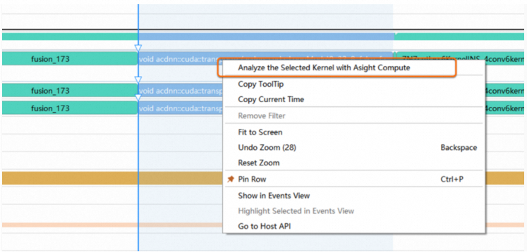
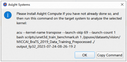
To analyze an underperforming kernel in more detail, select it in the Timeline View. Then, from the context menu, select Analyze the Selected Kernel with Asight Compute to copy the command for generating an Asight Compute report. Run this command in the Asight Compute command-line tool to generate the report. You can then analyze the report in the Asight Compute GUI tool.
2. Track PPU metrics
asys periodically samples device runtime metrics, such as resource utilization and IO throughput rate, and displays their changes over time in the Asight Systems GUI:
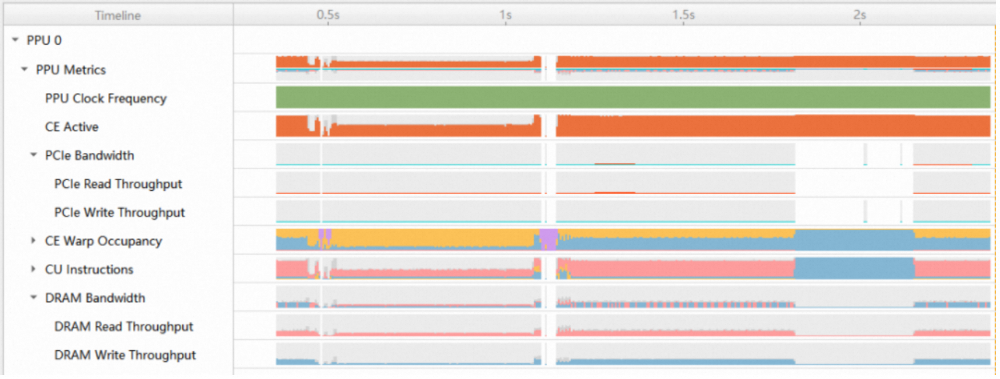
The GUI groups metrics by category and supports two summary display modes: Overlay and Stacked.
Use the --ppu-metrics-device option to specify which devices to sample. Use --ppu-metrics-device all to sample all devices. For example:
asys profile -t hggc --ppu-metrics-device all python test_linear.pyThis command samples all devices using the default metric set.
Use the --ppu-metrics-set option to specify the metric set. For example, --ppu-metrics-set throughput samples the metric set for IO throughput rate:
asys profile -t hggc --ppu-metrics-device all --ppu-metrics-set throughput python test_linear.pyYou can use the --ppu-metrics-device help option to view the list of available devices. You can specify multiple devices by using a , to separate them. For example, --ppu-metrics-device 0,1 indicates that only the runtime metrics for devices 0 and 1 are collected:
root@02892cb56ba5:~# asys profile --ppu-metrics-device help
Possible --ppu-metrics-device values are:
    all: Select all supported PPUs
    none: Disable PPU Metrics [Default]
    device ID list: comma separated device ID list(eg.: 0,1)

Available PPU metrics sampling devices are:
    0: PPU, PCI Bus ID: 00000000:10:00.0
    1: PPU, PCI Bus ID: 00000000:11:00.0
    2: PPU, PCI Bus ID: 00000000:CE:00.0
    3: PPU, PCI Bus ID: 00000000:CF:00.0
asys samples device metrics periodically. The default sampling frequency is 1,000 times per second (1 kHz). You can use the --ppu-metrics-frequency option to set the sampling frequency. For example, --ppu-metrics-frequency 10000 sets the sampling frequency to 10 kHz.
asys supports a wide range of device metrics. However, due to the capacity limit for performance data sampling, you can only sample a limited number of metrics at a time. asys provides several predefined metric sets. Use the --ppu-metrics-set help option to view the supported metric sets:
root@02892cb56ba5:~# asys profile --ppu-metrics-set help
Possible --ppu-metrics-set values are:
 ---------------- ---------------------------------------- --------------------------------------------
  Identifier       Description                              Enabled Metrics
 ---------------- ---------------------------------------- --------------------------------------------
  summary          Collect clock / memory / CU activity /   ce__cycles_elapsed.avg.per_second
                   Bus throughput information.              ce__cycles_active.avg.pct_of_peak_sustained_elapsed
                                                            gd__dispatch_count.avg.pct_of_peak_sustained_elapsed
                                                            ce__warps_active_accumulated.avg.pct_of_peak_sustained_elapsed
                                                            ce__warps_inactive_cu_active_accumulated.avg.pct_of_peak_sustained_elapsed
                                                            ce__warps_inactive_cu_idle_accumulated.avg.pct_of_peak_sustained_elapsed
                                                            cu__cycles_active.avg.pct_of_peak_sustained_elapsed
                                                            cu__ws_issue_active.avg.pct_of_peak_sustained_elapsed
                                                            cu__we_pipe_tensor_cycles_active.avg.pct_of_peak_sustained_elapsed
                                                            dram__exclude_hbm_bytes_read.sum.pct_of_peak_sustained_elapsed
                                                            dram__exclude_hbm_bytes_write.sum.pct_of_peak_sustained_elapsed
...
  throughput       Collect DRAM / PCIe / ICN link           kvd__transaction_hit_rate.pct
                   throughput information.                  ksd__transaction_hit_rate.pct
                                                            l2__transaction_hit_rate.pct
                                                            dram__exclude_hbm_bytes_read.sum.pct_of_peak_sustained_elapsed
                                                            dram__exclude_hbm_bytes_write.sum.pct_of_peak_sustained_elapsed
                                                            pcie__read_bytes.avg.pct_of_peak_sustained_elapsed
                                                            pcie__write_bytes.avg.pct_of_peak_sustained_elapsed
                                                            icnltx__bytes.sum.pct_of_peak_sustained_elapsed
                                                            icnlrx__bytes.sum.pct_of_peak_sustained_elapsed
...
You can also specify a custom list of metrics to sample. Use the --ppu-metrics-list help option to view descriptions of the supported metrics:
root@02892cb56ba5:~# asys profile --ppu-metrics-list help
Possible --ppu-metrics-list values are:

ce__cycles_active.avg
    Display Name:
        ce__cycles_active.avg
    Unit: cycle
    Description:
        # of cycles active on CE across CEs
...
kvd__transaction_hit_rate.pct
    Display Name:
        kvd__transaction_hit_rate.pct
    Unit: %
    Description:
        (%) hit rate of KVD cacheable requests
...
Use the --ppu-metrics-list option to specify a custom list of metrics, separating multiple metrics with a comma (,). asys merges the metrics from --ppu-metrics-list with those from --ppu-metrics-set and samples them together. For example, --ppu-metrics-list ce__cycles_active.avg,kvd__transaction_hit_rate.pct samples CE utilization and KVD cache hit rate:
asys profile -t hggc --ppu-metrics-device all --ppu-metrics-set none --ppu-metrics-list ce__cycles_active.avg,kvd__transaction_hit_rate.pct python test_linear.pyDue to the capacity limit for performance data sampling, when specifying a custom list of metrics with --ppu-metrics-list, the list must not exceed the device's capacity limit. Use the --check-ppu-metrics-list option to validate the metric list, separating multiple metrics with a comma (,):
root@02892cb56ba5:~# asys profile --check-ppu-metrics-list ce__cycles_active.avg,kvd__transaction_hit_rate.pct,pu__we_average_warps_issue_stalled_compute_sfu_raw_per_issue_active.ratio
Check sampling metrics list result: PASS.
Metrics list is suitable for PPU sampling capacity.Tip: Sampling device runtime metrics with asys might fail if another application is using the PPU performance counter resources. Sampling can fail for the following reasons:
-
Another asys application is already sampling device runtime metrics.
-
Another acu application is collecting trace data.
-
DCGM is collecting performance metrics. You can pause DCGM sampling by running
dcgmi profile --pause. -
Use PPU-SMI to check if the PPU performance counter and the HGML GPM service are busy.
-
ppu-smi -qQueries the status of the PPU performance counter. -
ppu-smi gpm --get-sample-stateChecks whether the HGML GPM service is enabled (the service uses the PPU performance counter when enabled). -
Run
ppu-smi gpm -s 0to pause output from the HGML GPM service and release the PPU performance counter.
-
3. HGTX tracing
Asight Systems supports HGTX tracing, letting you annotate your application's timeline with custom ranges. HGTX supports custom domains and offers both push/pop and start/end APIs.
The following example shows how to use HGTX:
#include <nvtx3/nvToolsExt.h>

for (int index = 0; index < 1000; ++index) {
    nvtxRangePushA("Loop");
    nvtxRangePushA("DoProcess");
    DoProcess();
    nvtxRangePop();
    ...
    nvtxRangePop();
}
This code pushes two nested HGTX ranges: Loop and DoProcess. The inner DoProcess() function calls several HGGC APIs. To collect the HGTX trace, run the following command:
asys profile -t hgtx -o test_report sampleAfter the trace is collected, the GUI displays the timeline as shown below:

The ranges are nested. The outer HGTX range, Loop, appears above the inner HGTX range, DoProcess. The Loop range encompasses the entire duration of the DoProcess range, including the runtime API calls made within that function.
Asight Systems also supports collecting and displaying user-specified colors for ranges:

4. OS Runtime tracing
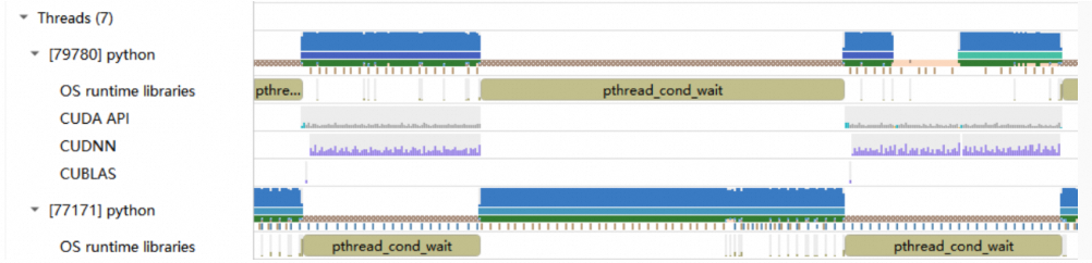
OS Runtime tracing (OSRT) identifies the root causes of CPU thread suspension, such as calls to pthread_mutex_lock and sleep. To enable OSRT, add osrt to the -t trace option:
-
Use the
--osrt-thresholdoption to specify the collection threshold. -
Use the
--osrt-backtrace-thresholdoption to specify the call stack backtrace threshold.
For example:
asys profile -t osrt --osrt-backtrace-threshold 80000 python /test_script/ops/test_linear.pyView the OSRT timeline in the GUI:
5. CPU and thread activity tracking
Asight Systems tracks how threads are scheduled across CPU cores. You can use the--sample or -s option in asys to trace your application's execution on each CPU. This feature also supports periodic collection of CPU execution call stacks, which are then aggregated to provide function timing statistics.
For example, the following command collects CPU execution information and specifies a sampling period for call stacks:
asys profile -s process-tree -b dwarf --sample-period 2000000 python test_linear.py-
-s process-treecollects CPU scheduling traces for the application's process tree. -
-b dwarfenables the collection of CPU execution call stacks. This is enabled by default and can be omitted. -
--sample-period 2000000specifies the sampling period for each CPU call stack, measured in CPU execution cycles. -
--sample-backtrace-depthspecifies the call stack depth for CPU sampling. The default is 24.
Tip:
-
Enabling CPU execution sampling can significantly increase the report file size. A smaller value for
--sample-periodhas a greater impact on your application's performance. -
The operating system may constrain the sampling period specified with the
--sample-periodoption, causing the actual sampling frequency to be lower than configured. -
When you specify a short sampling period with
--sample-period, some samples may be dropped due to throughput limitations.
5.1 CPU activity
This feature requires one of the following collection options:
-
--sample process-tree: Collects data for the process tree. -
--sample system-wide: Collects data for all processes on the system.
After you enable CPU sampling, you can view CPU activity:

In the image above, the "CPU Group" row shows overall CPU activity. Each node below it represents the workload of a specific core. A dense portion of the timeline indicates that the core was busy, while a blank area indicates it was idle. Dark blue indicates the main process's activity, and black indicates the activity of child processes. Each CPU core node on the left has a colored label that corresponds to the colors used in the thread rows.
The timeline tooltip shows which process and thread are currently executing on the CPU:

Select "Go to Thread Row" from the context menu to jump to the corresponding thread row:

Tip: CPU sampling has a high sampling rate and can increase the report file size. If you do not need CPU sampling, disable it by passing the -s none option to the asys command.
5.2 Thread scheduling
This feature requires one of the following collection options:
-
--sample process-tree: Collects data for the process tree. -
--sample system-wide: Collects data for all processes on the system.
When CPU sampling is enabled, the thread timeline appears as shown below:

The child nodes of a thread row show various API calls. The thread row itself displays its execution on different CPU cores across four sub-rows:
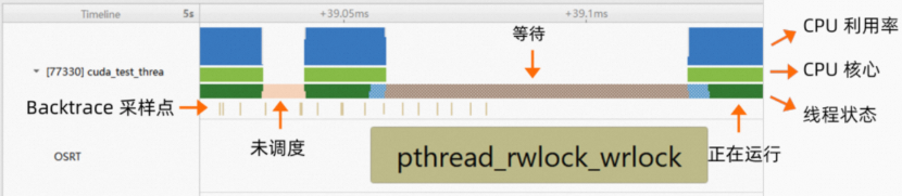
From top to bottom, the sub-rows are:
-
CPU utilization: Shows CPU resource usage.
-
CPU core: Indicates which core the thread is scheduled on. Its color corresponds to the label color of the CPU core node.
-
Thread state, which can be one of four states:
-
Running

-
Uninterruptible
-
Waiting
-
-
Calling OSRT
-
Backtrace sample point: A point where a sample was taken. The tooltip provides detailed call stack information.


Hover over an item to view more detailed information.
If you enable OSRT collection without CPU sampling, Asight Systems can estimate the thread state based on OSRT execution. Asight Systems considers time slices in OSRT as CPU idle and time spent outside OSRT as CPU busy, as shown in the following image:

In this case, there are two thread states:
-
Possibly Running
-
Possibly Waiting


If only backtrace sampling is enabled, the thread row displays sampling points:

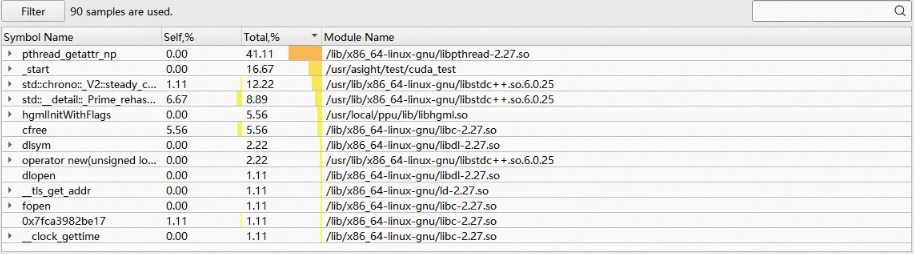
View function timing statistics for your application in the "Function View" at the bottom of the GUI:
5.3 CPU metrics collection
asys periodically collects various CPU runtime metrics, including hardware and software (operating system) metrics like IPC and cache miss rate, as shown in the following image:

Because CPU metrics collection is system-level tracing, you need to enable --event-sample=system-wide.
You can use --cpu-core-events to specify hardware metrics and use --cpu-core-events=help to view the specific metrics and their definitions. For example:
asys profile --event-sample=system-wide --cpu-core-events=1,2,3You can specify software (operating system) metrics with --os--events and view the specific metrics and their definitions with --os-events=help. For example:
asys profile --event-sample=system-wide --os-events=1,2,3asys provides several preset CPU collection metric sets. You can use the --cpu-core-events-set option to specify a hardware metric set and use the --cpu-core-events-set=help option to view the supported metric sets (the default is summary), for example
asys profile --event-sample=system-wide --cpu-core-events-set=cacheYou can use --os-events-set to specify a specific software metric set, and use the --os-events-set=help option to view the supported metric sets (the default is summary), for example
asys profile --event-sample=system-wide --os-events-set=faultVarious CPU metrics are collected periodically, and you can use --sample-period 2000000 to specify the collection period for each CPU metric in CPU execution cycles (the default value is 2,000,000).
6. API call stack tracing
asys collects call stack information for APIs like HGGC, OSRT, ACDNN, ACBLAS, CUDNN, and CUBLAS. You can set a threshold to capture call stacks for API calls that exceed a specified duration and control the maximum backtrace depth. Once you enable API call stack tracing, you can visualize function calls in the GUI's Function View as flame graphs, icicle graphs, and the Top Down, Bottom Up, and Flat tables.
6.1 Collect HGGC call stacks
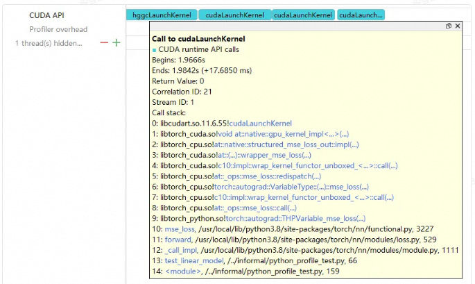
Use the following command to trace HGGC and collect call stack information:
asys profile -t hggc --hggcbacktrace all:1000 --hggc-backtrace-depth 24 python test_linear.py-
-t hggcenables HGGC tracing. -
--hggcbacktrace all:1000collects call stacks for all HGGC API calls that take longer than 1,000 nanoseconds (ns) to execute. -
--hggc-backtrace-depth 24sets the maximum HGGC call stack depth to 24 frames.
Hover over the timeline to view the call stack:
6.2 Collect OSRT call stacks
Use the following command to trace OSRT and collect call stack information:
asys profile -t osrt --osrt-backtrace-threshold 80000 --osrt-backtrace-depth 24 python /test_script/ops/test_linear.py-
-t osrtenables OSRT tracing. -
--osrt-backtrace-threshold 80000collects call stacks for OSRT API calls that take longer than 80,000 nanoseconds (ns) to execute. -
--osrt-backtrace-depth 24sets the maximum OSRT call stack depth to 24 frames.
The following image shows the call stack:
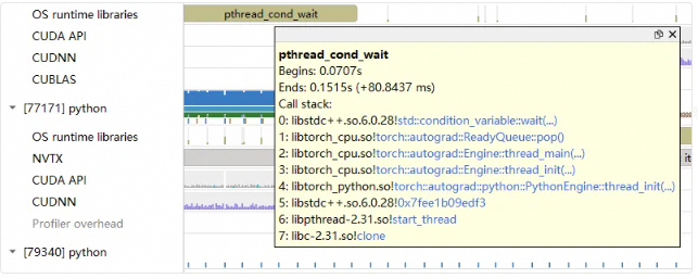
6.3 Collect ACDNN/ACBLAS call stacks
Use the following command to trace ACDNN and ACBLAS and collect call stack information:
asys profile -t acdnn,acblas --acompute-backtrace-threshold 80000 python /test_script/ops/test_linear.py
-
-t acdnn,acblasenables ACDNN and ACBLAS tracing. -
--acompute-backtrace-threshold 80000collects call stacks for ACDNN and ACBLAS API calls that take longer than 80,000 nanoseconds (ns) to execute.
The following image shows the call stack:
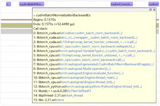
7. Memory usage tracing
7.1 PPU memory tracing
asys traces your application's PPU memory usage. It collects call stack information during device memory allocation and deallocation, then provides aggregated statistics based on this data. Enable memory usage tracing with the --hggc-memory-usage option. For example:
asys profile -t hggc --hggc-memory-usage true python test_linear.pyWhen memory usage tracing is enabled, Asight Systems displays PPU memory usage on the timeline, letting you analyze memory consumption, as shown below:

The device memory usage row shows PPU memory consumption during the program's execution and includes the following features:
-
Correlation with HGGC APIs.
-
Support for viewing call stacks.
-
Display of allocation and deallocation events in the Events View.
If a PPU memory allocation fails, Asight Systems marks it with a small red dot on the device memory usage row:

In the GUI's Device Memory View, you can view the data as flame graph and icicle graph visualizations, or in Top Down, Bottom Up, and Flat tables.
Tips:
-
Control the call stack collection depth with the
--hggc-backtrace-depthoption. The default depth is 24 frames. For example,--hggc-backtrace-depth 50specifies a maximum backtrace depth of 50 frames. -
This feature does not collect device memory freed by HGGC destructors upon process termination.
7.1.1 Memory timeline
Expand the device memory usage row or click the Toggle memory timeline details button on the right to display the memory timeline, as shown below:
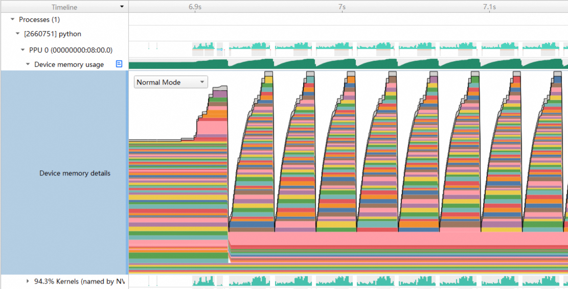
The figure above shows the details of each memory allocation, including its allocation and deallocation times. Very small allocations are merged and displayed at the top.
This view also supports two other modes: Group Mode and Group Coloring Mode.
Group Mode
This mode groups memory allocations by module, such as PyTorch or a communication library, letting you view the memory usage of a specific module, as shown below:
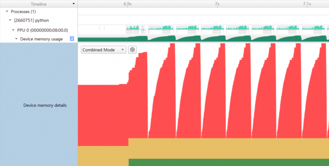
Click the button to the right of the mode selection drop-down list to open the Grouping Rules Dialog and configure grouping rules:
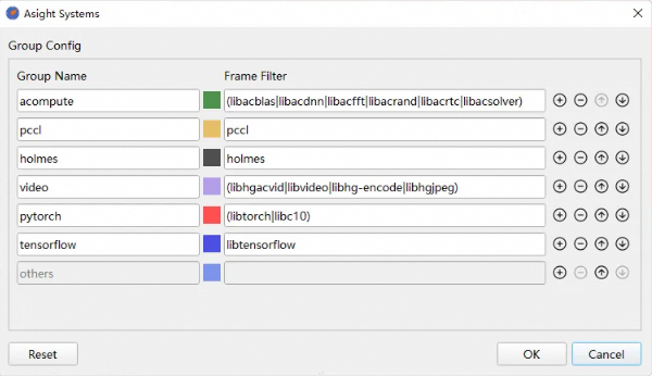
Asight Systems matches grouping rules from top to bottom. Each memory allocation can belong to only one group. You can click a color swatch to change the group's color.
Group Coloring Mode
This mode combines normal mode and Group Mode. Each memory allocation is still displayed individually, but its color corresponds to its group, as shown below:
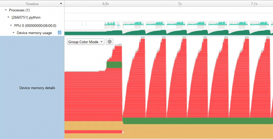
7.2 Host memory usage sampling
asys can periodically sample your application's host system memory usage. Enable this sampling with the --host-memory-sampling option and control the sampling frequency with the --host-memory-sampling-frequency option. For example:
asys profile -t hggc --host-memory-sampling true --host-memory-sampling-frequency 500 python test_linear.py
This sampling data lets you view how host memory usage for each process changes over time in the Asight Systems GUI:

The view displays two types of memory usage:
-
resident set size: The actual physical memory in use.
-
water mark: The peak physical memory usage during the collection period.
Tip: asys supports collecting system memory usage for the application's process tree, which includes the root process and its descendant processes. When system-wide tracing is enabled (-s system-wide), system memory usage sampling is disabled.
7.3 Heap memory tracing
asys traces your application's host dynamically allocated memory (also known as heap memory), such as memory allocated via malloc or new. It collects call stack information for these allocations and aggregates the data to provide usage statistics. Enable heap memory tracing with the --heap-memory-usage option. For example:
asys profile --heap-memory-usage true python test_linear.pyWith heap memory tracing enabled, you can view how each process's heap memory usage changes over time in the Asight Systems GUI:
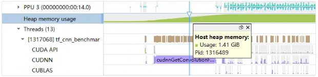
Click a point in time on the Heap memory usage graph to view information such as the flame graph or icicle graph of the dynamically allocated memory usage for the process up to that point, analyze memory leaks, and view statistics on memory usage and the number of allocations. For example:
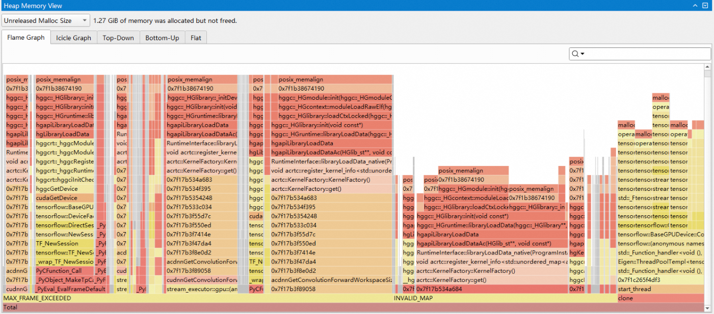
Tip: Select a time range by using Filter and Zoom in and click a point in time on Heap memory usage to view memory usage statistics from the selected start time to the clicked time, for example, to check for memory leaks during this period.
You can use the --heap-sampling-interval-bytes option to adjust the average sampling interval in bytes for dynamically allocated memory usage by asys. A smaller sampling interval improves the collection accuracy for smaller dynamically allocated memory usage, and also significantly increases the performance overhead of tracing and collection by asys.
Adjust the call stack depth for heap memory tracing with the --heap-backtrace-depth option, and the reporting interval for aggregated data with the --heap-report-interval option. For example:
asys profile --heap-memory-usage true --heap-sampling-interval-bytes 16777216 --heap-backtrace-depth 50 --heap-report-interval 2 python test_linear.py-
--heap-memory-usage true: Enables heap memory usage tracing. -
--heap-sampling-interval-bytes 16777216: Sets theaverage sampling interval in bytesto 16 MiB. -
--heap-report-interval 2: Specifies that dynamically allocated memory usage information is summarized and recorded every2 milliseconds.
Tips:
-
You can use the
--heap-sampling-interval-bytesoption to set theaverage sampling interval in bytes. This may cause asys to merge and report the usage of dynamically allocated memory that is smaller than this threshold to reduce the performance overhead of tracing and collection. -
Setting
--heap-sampling-interval-bytes=1forces asys to capture every single memory allocation. This significantly increases performance overhead and is not recommended for complex applications. -
You cannot use heap memory tracing when multi-node tracing is enabled with the
--multi-node-modeoption.
7.4 Pinned memory tracing
asys supports tracing your application's usage of pinned memory. It collects call stack information when pinned memory is allocated or freed and provides aggregated usage statistics based on this data. Pinned memory tracing is enabled by default when you enable both device memory tracing (--hggc-memory-usage) and host-side system memory sampling (--host-memory-sampling). For example:
asys profile -t hggc --hggc-memory-usage true --host-memory-sampling true python test_linear.py
Pinned memory tracing lets you view how each process's pinned memory usage changes over time in the Asight Systems GUI and see aggregated usage statistics for each API in your application, as shown below:
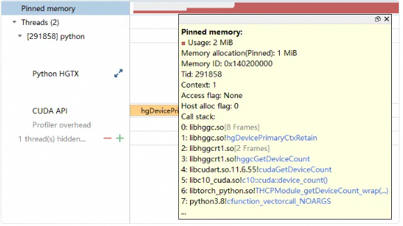
The figure above shows how pinned memory usage changes over time. The tooltip displays details about the allocation or deallocation that caused the change, including call stack information. The Events View also displays pinned memory events. In the GUI's Host Pinned Memory View, you can view the data as flame graphs, icicle graphs, or in Top Down, Bottom Up, and Flat tables.
Tips:
-
You can control the call stack collection depth with the
--hggc-backtrace-depthoption. The default depth is 24 frames. For example,--hggc-backtrace-depth 50specifies a maximum backtrace depth of 50 frames. -
The simultaneous collection of device and pinned memory usage is supported. Multiple options are separated by a
,, for example,--hggc-memory-usage device,pinned. -
This feature does not collect pinned memory freed by HGGC destructors upon process termination.
7.5 Unified memory usage scale
To help analyze OOM scenarios, you can unify the display scale for memory usage graphs. You can change this setting in the Options Dialog or the Timeline Options:

When Unified Memory Usage Scale is enabled, all memory usage timelines of the same type share a consistent vertical scale:

When Unified Memory Usage Scale is disabled, the vertical scale of each memory timeline is normalized to its own peak value:

8. Python tracing
8.1 Collecting Python call stacks
8.1.1 Periodic call stack sampling (Python sampling)
asys supports periodic sampling of a Python script's runtime call stack. The sampled data, including function names, filenames, and line numbers, appears in the Asight Systems GUI:
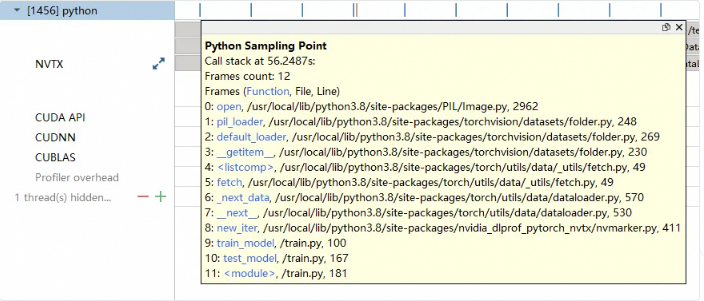
Use the --python-sampling option to enable periodic Python call stack sampling and the --python-sampling-frequency option to control the sampling frequency. For example:
asys profile --python-sampling true --python-sampling-frequency 1000 python launch.py-
--python-sampling true: Enables periodic sampling of the Python call stack. The default is true. -
--python-sampling-frequency 1000: Sets the sampling frequency. The range is 1 Hz to 1 kHz. The default is 500 samples per second (500 Hz). -
--python-backtrace-depth: Sets the maximum call stack depth to record. The default is 24.
8.1.2 Capturing call stacks on events (Python backtrace)
asys can capture the current Python call stack when a specific event is traced. asys then combines it with the C call stack to display the complete call chain.
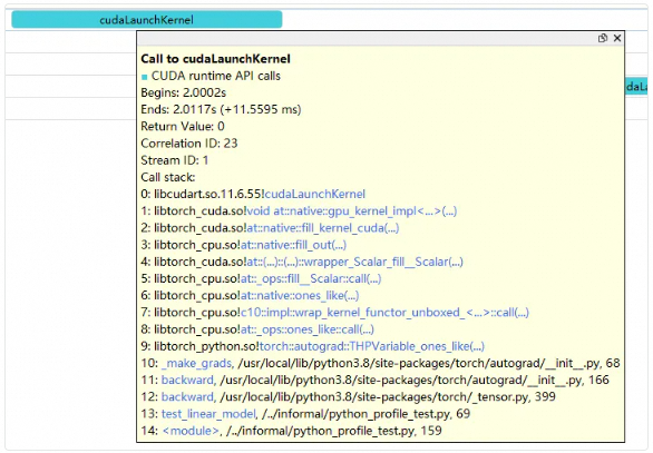
Enable this feature with --python-backtrace and control the call stack depth with --python-backtrace-depth. Python backtrace is currently supported for the following events:
-
hggc
For example:
asys profile --python-backtrace=hggc python launch.py -
device memory / pinned memory
For example:
asys profile --hggc-memory-usage=true --host-memory-sampling=true --python-backtrace=hggc python launch.py
Note:
-
asys supports call stack collection for Python versions 3.8 to 3.12.
-
asys does not currently support call stack collection for applications launched with an aliased Python interpreter (an executable not named
pythonorpython3).
8.2 Tracing Python functions
asys lets you trace Python functions without modifying the source code. These traces appear as HGTX ranges:

Use the --python-functions-trace option to specify which functions to trace. The following modes are supported:
|
Value |
Description |
|
none |
Default value. No functions are traced. |
|
all |
Traces all functions in the Python application. |
|
module:<module_name> |
Traces all functions in the specified module(s), including their submodules. Use a comma to separate multiple modules (e.g., module:torch,threading). |
|
<json_file> |
Traces functions specified in the given JSON file. |
Use the --python-functions-threshold option to trace only those Python functions whose runtime exceeds a specified threshold. The unit is nanoseconds (ns), and the default is 80,000 ns.
You can specify functions in a JSON file in the following ways:
-
Specify only the module. This traces all functions within that module, including its submodules. For example, if you specify
torch, all functions intorch.nnwill also be traced.[ { "module": "torch.nn.functional" }, { "module": "threading" } ] -
Specify the module (using its full path) and a list of function names under the
functionskey. You can also define a custom domain; the default is 'Python Hgtx'.[ { "module": "torch.nn.functional", "domain": "Torch Domain", "functions": ["sigmoid","log_softmax"] } ] -
Within the
functionslist, you can override properties for individual functions. If a function object specifies amodule, it overrides the parent module setting. If it specifies adomain, the function will be displayed in multiple domains.[ { "module": "torch.nn.functional", "domain": "Parent Domain", "functions": ["sigmoid", {"function": "Adadelta.step", "module": "torch.optim.adadelta", "domain": "Child Domain"}] } ]
You can mix these JSON formats. If there are conflicting rules, the last specified rule takes precedence.
For example, to trace all functions in the torch module and set the runtime threshold to 1,000 ns:
asys profile --python-functions-trace module:torch --python-functions-threshold 1000 python xx.pyNote:
-
asys supports function tracing for Python 3.8 and later.
-
In multithreading scenarios, there may be a delay between when a child thread is created and when asys collects its activity.
-
asys does not support specifying functions in the
__main__module. -
Function tracing may be inaccurate when the application forks a process.
9. PCCL activity tracking
asys can collect PCCL activity events for you to inspect. Enable this collection with -t pccl. For example:
asys profile -t pccl hggc python test_pccl.pyThe timeline is shown below:
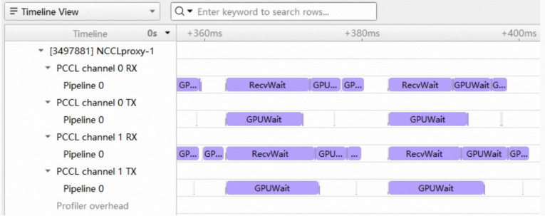
The PCCL timeline categorizes events first by channel, and then by pipeline within each channel.
10. RDMA NIC runtime metrics tracking
asys can periodically collect runtime metrics for the system's RDMA NICs, such as received and transmitted byte counts, average receive and transmit packet sizes, and congestion control information. The Asight Systems GUI visualizes how these metrics change over time:
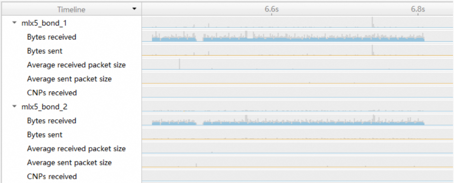
Supported metrics include:
-
Network receive speed
-
Network transmit speed
-
Network receive packet size
-
Network transmit packet size
-
Network receive CNP rate
-
Network transmit CNP rate
-
Send wait
When you select a time range, a tooltip displays the average network transfer speed within that range, as shown below:
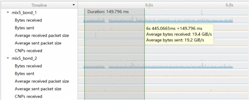
Use the --nic-metrics option to enable NIC metric collection. asys will then collect runtime data for all NIC devices and display the active devices in the GUI. For example:
asys profile --nic-metrics true ./all_reduce_perf-
--nic-metrics true: Enables NIC runtime metric collection.
Use the --nic-device-include option to filter NIC devices by name using regular expressions. Specify multiple rules as a comma-separated list. If a NIC's name matches a rule, asys enables collection for that device. For example:
asys profile --nic-metrics true --nic-device-include "bond" ./all_reduce_perf-
--nic-device-include "bond": Collects metrics for NIC devices whose names contain "bond".
asys profile --nic-metrics true --nic-device-include "bond,eth" ./all_reduce_perf-
--nic-device-include "bond,eth": Collects metrics for NIC devices whose names contain either "bond" or "eth".
Use the --nic-metrics-frequency option to control the sampling frequency. The valid range is from 1 Hz to 100 kHz, with a default of 1 kHz.
asys profile --nic-metrics true --nic-metrics-frequency 10000 ./all_reduce_perfNote:
-
Due to limitations of the RDMA driver interface, the actual sampling frequency may not reach the configured value. If the specified frequency exceeds the driver's capability, asys defaults to the maximum supported sampling frequency.
-
When launching a Docker container, use
--network host --device=/dev/infiniband.