Analyze reports
1. Expert system
The Expert System is an intelligent analysis system within Asight Systems that helps you identify common performance issues. It analyzes events in a report and provides optimization suggestions to help you improve performance.
1.1 From the console
In the GUI, you can switch to the Expert System page from the tab at the bottom of the screen, as shown below.
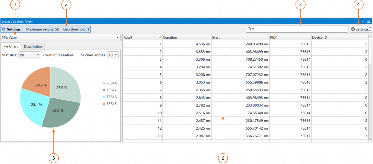
Rule list: Select analysis rules.
Current parameter configuration: Hover over this area to view detailed parameter information.
Search box: Supports search and filter modes.
Rule parameter configuration: A dialog box for changing the configuration for the current rule.
Pie chart and optimization suggestions: Displays a pie chart of the current rule's analysis results and related optimization suggestions. Switch between them using the tabs at the top.
Analysis results: Shows the results for the current rule. You can export the analysis results from the context menu.
1.1.1 Analysis time range
You can use the filter feature in the Timeline View to specify a time range. The Expert System will only analyze events within this range. In the Timeline View, click and drag to select a time range. Then, right-click and choose Filter and Zoom in to set the analysis time range.
1.1.2 Timeline view navigation
For some rules, you can navigate to the Timeline View. You can choose how to navigate from the context menu.
1.1.3 Analysis pie chart
In addition to a table, the Expert System can display analysis results in a pie chart.
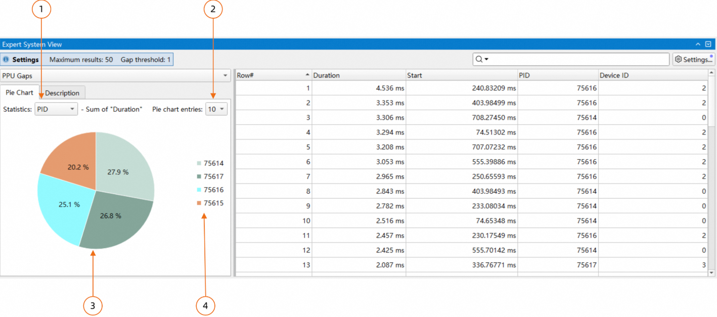
In the preceding figure:
The pie chart categorizes each row from the table on the right by a specified key, such as "PID". For each category, it sums the values from the "Duration" column. The chart then shows each category's percentage of the total duration. You can select the key from the combo box.
Specifies the number of slices to display.
Pie chart: Each slice shows a specific PID's total duration as a percentage of the overall duration.
Legend: Shows the PIDs from the chart, sorted in descending order by duration.
You can click a slice in the pie chart to filter the table. The table will then show only the rows corresponding to the selected key, as shown in the following figure.
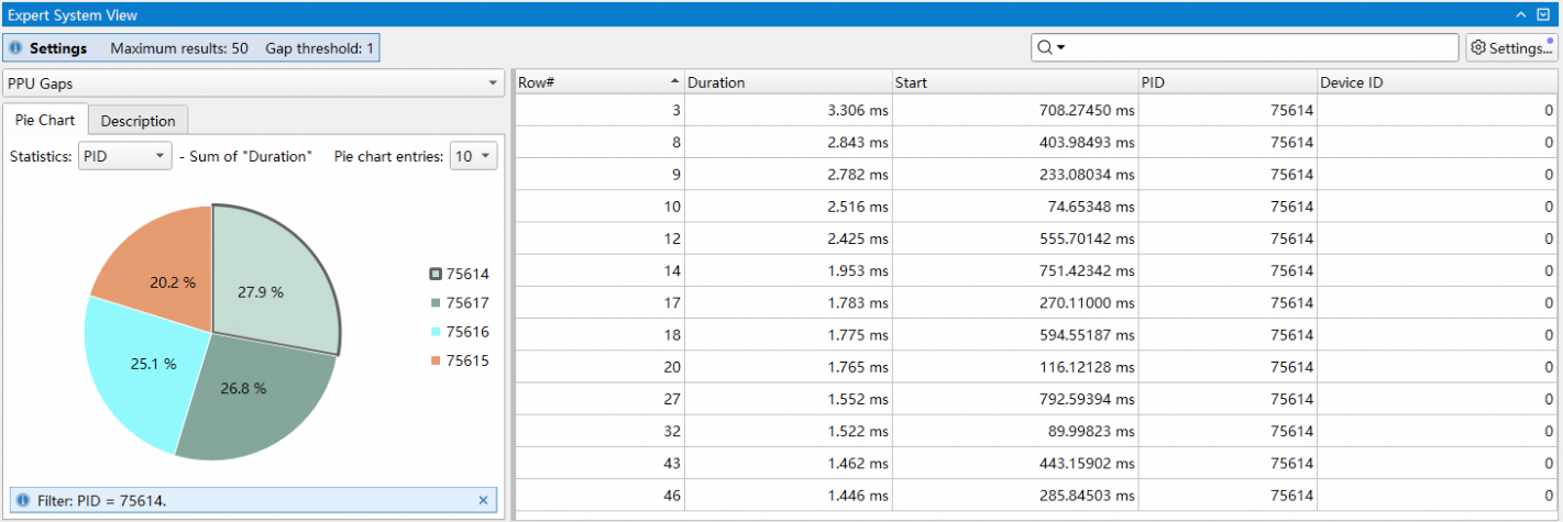
The figure shows that clicking the slice for PID 75614 filters the table on the right to show only items for that PID, hiding all others. To reset the table, click the same slice again or click a blank area of the chart.
1.2 From the CLI
Use the asys analyze subcommand to analyze an asysrep file and generate reports. The syntax for the asys analyze subcommand is: asys analyze [option] <file.asysrep>.
1.2.1 Analysis rule
The asys analyze subcommand supports multiple analysis rules. To view detailed descriptions of all supported rules, run asys analyze --help-rules ALL.
Use the --rule option to specify one or more analysis rules. You can use this option multiple times or provide a comma-separated list. If you do not specify a rule, the command uses a default set of rules to generate the report.
For example, to generate a report using the ppu_gaps and ppu_time_util analysis rules, run the following command:
asys analyze --rule ppu_gaps,ppu_time_util report.asysrep1.2.2 Report output format
The asys analyze subcommand lets you specify the output format for the report using the --format option. To view supported output formats and help information, run asys analyze --help-formats ALL.
column: The default format for terminal output. It prints data in an easy-to-read list format. The following options are supported:
Unit Settings: Set the unit and precision of the output data.
csv: The default format for file output. It prints data in CSV format, which is easy to export for further processing. The following options are supported:
Unit Settings: Sets the unit and precision for the output data.
The Unit Settings option allows you to specify the unit for displaying a specific type of data. The supported types and unit options are listed as follows:
ratio: For ratio or percentage data. Supported units include:%or.1%: One decimal place..2%: Two decimal places..3%: Three decimal places.
For example, to specify list-style output and set the precision for ratio data to three decimal places, run the following command:
asys analyze -r ppu_time_util --format column:ratio=.3% report.asysrep1.2.3 Report output destination
Use the --output option to specify the report's output destination. Three destinations are supported: printing to the console, saving to a file, or piping to another command. By default, the command prints results to the console.
Use --output % to print the report to the console. For example:
asys analyze --output % --rule ppu_gaps report.asysrepIf you use --output to save the output to the directory of the asysrep report, asys automatically generates an output filename based on the asysrep report's filename, the specified analysis type, and the output format. The output filename uses the format <report_name>_<rule_name>.<format>. For example, if you use --output to generate a ppu_gaps analysis report for report.asysrep in the report's directory, the output file is named report_ppu_gaps.csv.
asys analyze --output . --rule ppu_gaps report.asysrepUse --output @post_command to pipe the output to post_command for post-processing. This option pipes the analysis report to the specified command. For example, to find results containing the keyword 1142417, use the grep command:
asys analyze --output "@grep 1142417" --rule ppu_gaps report.asysrep1.2.4 Output columns
The asys analyze subcommand lets you specify which columns to include in each report type. When you generate the report, it includes only the specified columns. To specify columns, use the column option with the rule name, separating multiple column names with a forward slash (/). For example:
asys analyze -r "ppu_gaps:column=Duration/Device ID" -r "ppu_time_util:column=In-Use/Device ID" report.asysrepThe
ppu_gapsreport will only include theDurationandDevice IDcolumns.The
ppu_time_utilreport will only include theIn-UseandDevice IDcolumns.
1.2.5 Analysis time range
Use the --filter-time option to specify the analysis time range. The format is start_time/end_time in nanoseconds, representing offsets from the start of data collection. You can omit either the start time or the end time. For example, to analyze trace data from 10 seconds to 20 seconds, run the following command:
asys analyze --filter-time 10000000000/20000000000 --rule ppu_gaps report.asysrepUse the --filter-hgtx option to specify the analysis time range by using an HGTX annotation. If the --filter-hgtx option is specified, the --filter-time option is ignored.
The --filter-hgtx option allows you to specify the name, domain, and index of the HGTX range to match. The format is range_name@domain/index. If the matched HGTX range does not have a domain, you can omit @domain. Otherwise, @domain is required.
By default, asys uses the first matched HGTX range as the analysis time range, so you can omit /index. To match by index, use /index, where the index starts from 0.
For example, to use the time range of the first matched HGTX range named self_attention with no domain, run the following command:
asys analyze --filter-hgtx self_attention --rule ppu_gaps report.asysrepFor example, to use the time range of the ninth matched HGTX range (index 8) named pcclGroupEnd in the NCCL domain, run the following command:
asys analyze --filter-hgtx "pcclGroupEnd@NCCL/8" --rule ppu_gaps report.asysrepTips:
The timestamp information in the asys analyze output may vary depending on the
--ruleoption. To standardize the timestamp information, you can specify the--ts-normalize trueoption to convert timestamps to UTC time.asys analyze supports the
--ts-shiftoption to manually adjust the timestamp offset, and this option can be used with--ts-normalize.
1.3 Expert system rules
1.3.1 PPU long idle time analysis
Analyzes and summarizes long periods of PPU idle time (PPU bubbles) from an asysrep report. It sorts the results in descending order by idle duration.
For each PPU device, this rule checks each process to find idle periods that meet a specified duration threshold. The rule performs this check within the time range from the first PPU activity to the last PPU activity on that device.
Required data collection option: --trace hggc
Analysis rule
A PPU is considered idle when none of the following activities are occurring:
Executing a kernel
Executing a memcpy or memset operation
Executing video encoding or decoding
The rule identifies idle periods on a per-process, per-PPU basis. If an idle period is longer than the threshold set by the gap parameter, the rule includes it in the results.
The results are sorted in descending order by idle duration.
The following table describes the columns in the ppu_gaps report.
Row# : Row number of the PPU gap
Duration [ns] : Duration of the PPU gap
Start [ns] : Start time of the PPU gap
PID : Process identifier
Device ID : PPU device identifier
Command-line usage
asys analyze --rule ppu_gaps report.asysrepWhen you use the --rule option to select ppu_gaps, you can concatenate multiple :options to specify the parameters for the analysis. You can run asys analyze --help-rules ppu_gaps to view detailed help information. The following are examples of supported options:
rows=<limit>: Limits the number of PPU long idle time results to display.gap=<threshold>: Sets the time threshold for long idle periods, in milliseconds.
For example, to analyze long PPU idle time with an idle time threshold of 20 ms and output the top 10 longest idle periods, run the following command:
asys analyze --rule ppu_gaps:rows=10:gap=20 report.asysrepThe following is an example of the report output:
Row#,Duration,Start,PID,Device ID,
1,1232895501,126020393150,1142419,6,
2,1219910832,126016153086,1142417,4,
3,1219804936,126017799911,1142416,3,
...
GUI guide
Settings
Maximum number of results: Limits the number of PPU long idle time results to display. The default value is 50.
Minimum duration of PPU gaps in ms: Specifies the time threshold for long idle periods, in
milliseconds. The default value is 500.
Table context menu functions
Allows you to highlight or zoom to the selected range in the Timeline View.
Pie chart statistics: Aggregates the total long idle time for each process or device. Use the pie chart to see which process or device has more PPU bubbles.
1.3.2 PPU utilization analysis
Analyzes and summarizes the time-based utilization of PPUs from an asysrep report. It sorts the results in ascending order of utilization. For each PPU device, this rule checks each process based on the selected Range Mode. It divides the time range into equal-sized chunks and calculates the PPU utilization for each chunk.
If you select the PPU Active Time Range mode, the analysis time range starts from the first PPU operation on the device and ends at the last PPU operation. If you select the Filtered Time Range mode, the time range matches the specified filter time range. Note that this rule measures time utilization, not resource utilization. Therefore, a simple memcpy operation has the same utilization value as a complex kernel that uses all available resources. If multiple operations overlap in time, their busy time is counted only once, so the utilization of a single chunk cannot exceed 100%. The results show chunks with a utilization percentage below the specified threshold. If multiple consecutive chunks have low utilization, the rule merges them into a single result with a weighted average utilization. As a result, the duration of each result entry may vary.
Required data collection option: --trace hggc
Analysis rule
A PPU is considered busy when any of the following activities are occurring:
Executing a kernel
Executing a memcpy or memset operation
Executing video encoding or decoding
At the per process, per PPU level, the PPU's total active time is calculated as the duration from the start of the first activity to the end of the last activity.
Total active time is divided into time segments of equal length according to the chunks parameter, and for each time segment, the PPU time utilization is calculated as: Busy time / Time segment length.
Time periods with utilization below the threshold parameter are aggregated into the statistical results. If multiple adjacent time periods all have utilization below the threshold parameter, they are merged, and their combined utilization is calculated and output as the statistical result.
The results are sorted in ascending order of utilization.
Tips:
For activities that overlap in time, such as kernels or memcpy operations, the overlapping time is counted only once. The utilization for any time period cannot exceed 100%.
In the GUI, you can specify a filtered time range by selecting an area in the Timeline View, right-clicking, and choosing
Filter and Zoom in.Adjust the
chunksandthresholdparameters to calculate the PPU time utilization for the entire report. For example:asys analyze --rule ppu_time_util:threshold=100:chunks=1:range-mode=full report.asysrep.
The columns in the ppu_time_util table are described as follows:
Row# : Row number of the chunk
In-Use [%] : Percentage of time the PPU is being used
Duration [ns] : Duration of the chunk
Start [ns] : Start time of the chunk
PID : Process identifier
Device ID : PPU device identifier
Command-line usage
asys analyze --rule ppu_time_util report.asysrepWhen you use --rule to select ppu_time_util, you can specify parameters for the analysis by concatenating multiple :options. You can run asys analyze --help-rules ppu_time_util to view detailed help information. Examples of supported options are as follows:
rows=<limit>: Limits the number of low PPU utilization periods to display.threshold=<percent>: Sets the percentage threshold for PPU busy time.chunks=<number>: The number of chunks to divide the total PPU active time into.range-mode=<mode>: The selection mode for the statistics time range, which supports theactiveandfullmodes:active: The default mode. The time range starts with the first PPU activity and ends when the last PPU activity finishes.full: The time range is set to the statistics time range that you specify. If no statistics time range is specified, the overall time range of the statistics report is used.
compute-pipe=<index_list>: Specifies the list of Compute Pipes to include in the statistics. Use a/to separate multiple Pipe Indexes. If you do not specify this parameter, statistics for all Compute Pipes are collected by default. You can use this parameter to analyze time utilization when Multi-Process Service (MPS) mode is enabled.
For example, to analyze PPU utilization with a utilization threshold of 60%, divide the time into 80 chunks, and output the top 20 results with the lowest utilization, run the following command:
asys analyze --rule ppu_time_util:rows=20:threshold=60:chunks=80 report.asysrepThe following is an example of the report output:
Row#,In-Use,Duration,Start,PID,Device ID,
1,0.000000,12411,124667294244,1142418,5,
2,0.000000,7648,124667369358,1142419,6,
3,0.000000,7648,124667378918,1142419,6,
4,2.425268,7092,124667285970,1142418,5,
5,4.258319,7092,124667278287,1142418,5,
...
GUI guide
Settings
Maximum number of results: Limits the number of low PPU utilization periods to display. The default value is 50.
MPS Compute Pipe index: Specifies the MPS Compute Pipe indexes to include in the analysis. The default value is All, which analyzes all Compute Pipes.
Minimum percentage of PPU utilization: Sets the percentage threshold for PPU busy time. The output includes periods where PPU utilization is below this value. The default value is 50.
Number of equal-duration chunks: Specifies the number of chunks to divide the total PPU active time into. The default value is 100.
Time range mode: Sets the mode for the analysis time range.
PPU Active Time Range: Default mode. The time range starts with the first PPU activity and ends with the last PPU activity.Filtered Time Range: The statistics time range that you specify. If you do not specify a statistics time range, this is the overall time range of the statistics report.
Table context menu functions
Allows you to highlight or zoom to the selected range in the Timeline View.
Pie chart statistics: Aggregates the duration of low-utilization periods for each process or device. Use the pie chart to see which process or device has lower utilization.
2. Statistical system
The statistics system, a key feature of Asight Systems, aggregates data from reports to provide a comprehensive overview of application performance.
2.1 Statistics system in the GUI
Like Function View, you can switch to the statistics system by using the tab at the bottom, as shown below:
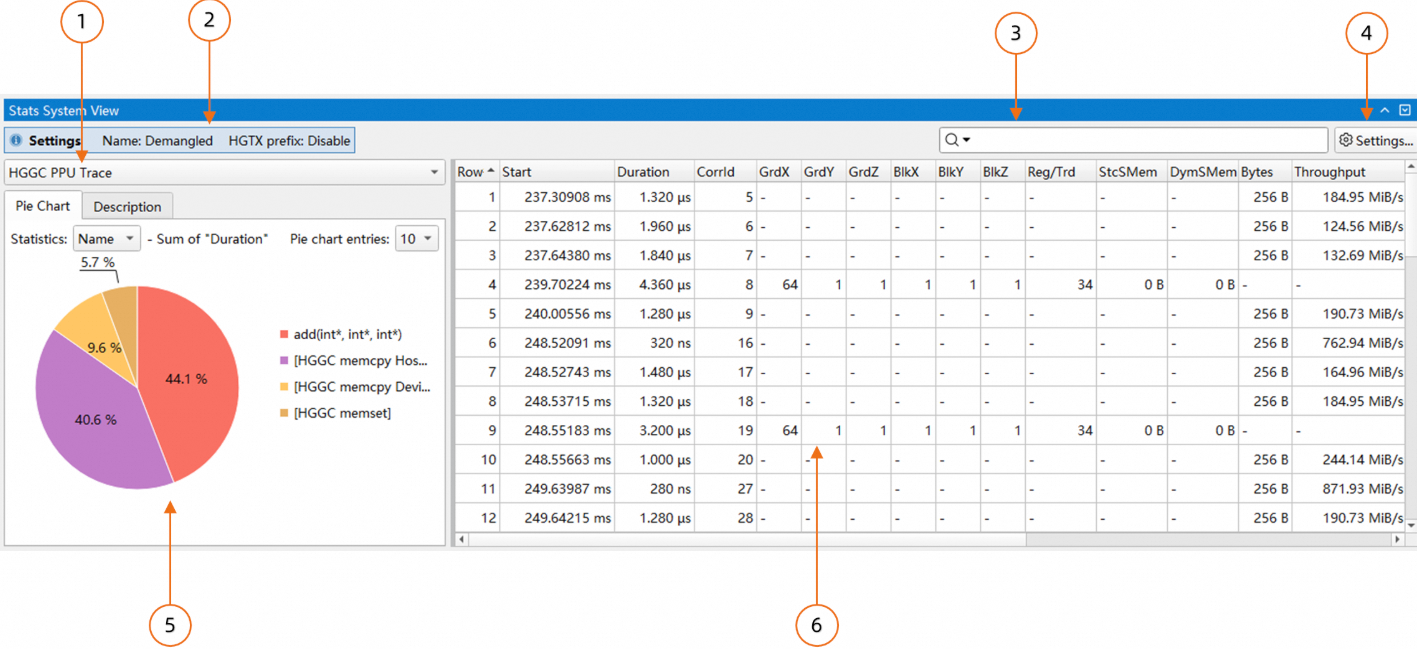
Rule list: Select statistics rules.
Current parameter configuration: Hover over this area to view detailed parameter information.
Search box: Supports both search and filter modes.
Statistics rule configuration dialog box: Changes the configuration for the current statistics rule.
Pie chart and optimization suggestions: Displays a pie chart of the statistical results and related optimization suggestions. Switch between these views using the tabs at the top.
Results table: Displays the analysis results for the current rule. You can export the results from the context menu.
2.1.1 Set the time range
Use the filter feature in Timeline View to set a time range for analysis. The statistics system analyzes only the events within this specified range. To set the range, click and drag in the Timeline View to select an area. Then, right-click the selection and choose Filter and Zoom in.
2.1.2 Navigation to Timeline View
For some rules, such as Trace and Detail rules, you can navigate from the table to the Timeline View. To do this, open the context menu in the table and select the appropriate navigation option.
2.1.3 Pie chart of statistical results
In addition to a table, the statistics system can also display results as a pie chart:
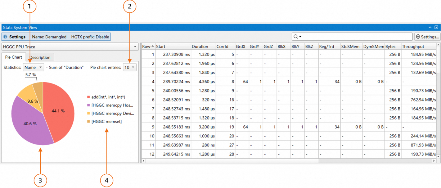
In the figure above:
The pie chart groups data from the table by a key, such as "Name". It then sums the "Duration" values for each group and displays each sum as a percentage of the total "Duration". You can select the key using the combo box.
Sets the number of slices to display.
Pie chart: Each slice shows a "Name" category's "Duration" as a percentage of the total "Duration".
Legend: Lists the "Name" categories from the chart, sorted by "Duration" in descending order.
Clicking a slice in the pie chart filters the table to show only the rows for that key, as shown below:
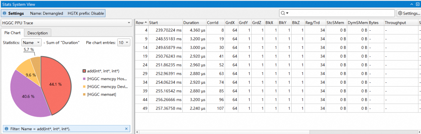
In the figure above, clicking the add(int*,int*,int*) slice filters the table to show only items with that name. To clear the filter, click the slice again or click a blank area in the pie chart.
2.1.4 Calculating column sums from selected rows
In the statistics system, some rules let you calculate column sums for selected rows. The table header displays the results, as shown below:
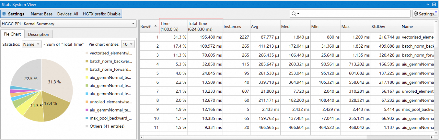
In the figure above, the first three rows are selected. The table header displays the sum of the "Time" and "Total Time" values for these selected rows.
2.2 Use the statistics system from the CLI
Use the asys stats command to perform statistical analysis on a specified report. It provides efficient statistics and trace data export capabilities. You can output the analysis results to the console, a file, or a command pipeline for easy viewing and further processing. You can also view some of these results in the Asight Systems GUI.
The syntax for the stats subcommand is: asys stats [option] <file.asysrep>
2.2.1 Specify the report type
asys stats supports multiple statistics report types. To view detailed descriptions of all supported report types, run asys stats --help-reports ALL.
Use the --report option to specify the statistics report type. You can use this option multiple times or provide a comma-separated list of report types. If you do not specify a statistics report type, the command uses the default report type.
For example, to generate a report with the hggc_ppu_kern_sum and device_memory_usage_summary statistics report types:
asys stats --report hggc_ppu_kern_sum,device_memory_usage_summary report.asysrep2.2.2 Specify the report format
The asys stats command supports the --format option to specify the output format of a statistical report. Run asys stats --help-formats ALL to view the supported output formats and help information.
column: The default format for terminal output. It prints data as an easy-to-read list. It supports the following options:Unit Settings: Set the unit and precision of the output data.
csv: The default format for file output. It prints data in CSV format for easy export and further processing. It supports the following options:Unit Settings: Set the unit and precision of the output data.
The Unit Settings option allows you to specify the unit used to display a specific type of data. The supported types and unit options are listed as follows:
ratio: For ratio/percentage data. Supported units:%or.1%: Accurate to one decimal place..2%: Accurate to two decimal places..3%: Accurate to three decimal places.
For example, to specify list-style output and set the precision for ratio data to three decimal places:
asys stats -r hgtx_ppu_proj_sum --format column:ratio=.3% report.asysrep2.2.3 Specify the output destination
You can use the --output option to specify the output type for the report. Three output types are available: printing to the console, outputting to a file, or outputting to a command. If this option is not specified, the report is printed to the console by default.
Use --output % to specify the console as the output destination. For example:
asys stats --output % --report hgtx_sum report.asysrepIf you use --output . to save the output to the same directory as the asysrep report, asys generates the output file name based on the asysrep report file name, the specified statistics report type, and the output format. The output file name format is <file_name>_<report_name>.<format>. For example, if you use --output to generate a statistics report of the hggc_api_sum type from report.asysrep in the same directory, the local report file is named report_hggc_api_sum.csv.
asys stats --output . --report hggc_api_sum report.asysrepUse --output @post_command to pipe the output to a post_command for further processing. This pipes the statistics report content through a command pipeline to the specified command. For example, to find results containing the keyword 1142417 using grep:
asys stats --output "@grep 1142417" --report device_memory_usage_summary report.asysrep2.2.4 Specify output columns
asys stats lets you specify which columns to include for each statistics report type. The generated report includes only the specified columns. To specify columns, use the column option with the report type, separating multiple column names with a forward slash (/). For example:
asys stats -r "hggc_ppu_kern_sum:column=Time/Name" -r "hgtx_ppu_proj_sum:column=Range/Total Proj Time" report.asysrepThe statistics report
hggc_ppu_kern_sumwill only include theTimeandNamecolumns.The statistics report
hgtx_ppu_proj_sumwill only include theRangeandTotal Proj Timecolumns.
2.2.5 Specify the time range
Use the --filter-time option to specify the statistics time range. The format is start_time/end_time, where each value is an offset in nanoseconds from the start of data collection. You can omit the start or end time. For example, to analyze trace data from 10 seconds to 20 seconds:
asys stats --filter-time 10000000000/20000000000 --report device_memory_usage_summary report.asysrepYou can use the --filter-hgtx option to specify the time range for statistics with HGTX annotations. When the --filter-hgtx option is specified, the --filter-time option is ignored.
Use the --filter-hgtx option to specify the name, domain, and match index of the target HGTX range. The format is range_name@domain/index. If the matched HGTX range does not have a domain, you can omit @domain; otherwise, you must include @domain.
By default, asys uses the first matched HGTX range as the statistics time range, so you can omit the /index part. To specify a particular match, use /index, where the index is 0-based.
For example, to use the time range of the first matched HGTX range named self_attention with no domain:
asys stats --filter-hgtx self_attention --report device_memory_usage_summary report.asysrepFor example, to use the time range of the ninth matched HGTX range (match index 8) named pcclGroupEnd in the NCCL domain:
asys stats --filter-hgtx "pcclGroupEnd@NCCL/8" --report device_memory_usage_summary report.asysrepTips:
The timestamp information from asys stats may vary depending on the
--reportoption. To ensure consistency, you can specify the--ts-normalize trueoption, which converts timestamps to UTC time.You can manually adjust the timestamp offset using the
--ts-shiftoption. This option can be used with--ts-normalize.
2.3 Statistics system rules
2.3.1 Device memory usage grouping summary
This feature analyzes and aggregates PPU device memory usage records from an asysrep report across multiple usage modes. It groups memory usage by categories (such as operator library or framework) and outputs a summary and detailed information for each group.
Required asys data collection option: --hggc-memory-usage device
Statistical rules
It aggregates unreleased PPU device memory usage records on a per-process, per-PPU basis.
For each unreleased memory usage record, the system matches a group rule based on the call stack information at the time of memory allocation, including the order of frames and the keywords matched within each frame.
If a memory usage record matches multiple groups, the output group information will display all the groups, separated by a /.
The tool calculates the total memory usage for each group combination and sorts the results in descending order by this total.
The device_memory_usage_detail table includes the following columns:
Row# : Row number of the device memory usage
PID : Process identifier
Device ID : PPU device identifier
Group List : List of groups the memory usage belongs to, separated by '/'
Time [ns] : Memory usage timestamp
TID : Thread identifier
Context ID : Context identifier
Memory : Memory identifier
Size [bytes] : Memory usage size
Access Flag : Memory access flag
Event ID : Memory usage event identifier
The device_memory_usage_summary table includes the following columns:
Row# : Row number of the device memory usage
PID : Process identifier
Device ID : PPU device identifier
Group List : List of groups the memory usage belongs to, separated by '/'
Memory Usage [bytes] : Device memory usage
Command-line usage
Use the -r <rule>:usage-mode=<mode> option to specify the usage mode.
The device_memory_usage_detail rule supports two usage modes:
'all': Exports memory traces of both allocations and frees.
'unreleased': Exports memory traces of unreleased allocations (potential memory leaks). (default)
The device_memory_usage_summary rule supports four usage modes:
'alloc-count': Summarizes the number of memory allocations.
'alloc-size': Summarizes the total size of memory allocations.
'unreleased-count': Summarizes the number of unreleased allocations.
'unreleased-size': Summarizes the total size of unreleased allocations. (default)
Use the --callstack-group-config option to add grouping rules. You can use the :match-first-group option to assign a record to the first matching group only. By default, the tool assigns records to all matching groups.
Use the --report option to specify a group statistics report. The following is an example:
asys stats -r device_memory_usage_summary:usage-mode=unreleased-size:match-first-group \
--callstack-group-config "acompute=(libacblas|libacdnn)" \
--callstack-group-config "launch_kernel=libtorch/LaunchKernel" \
--callstack-group-config "loss=loss.py" \
report.asysrep
-r device_memory_usage_summary: Specifies the device memory usage summary report.:usage-mode=unreleased-size: Summarizes the size of unreleased memory.:match-first-group: Assigns each record to only the first group it matches.--callstack-group-config "acompute=(libacblas|libacdnn)":Creates a group named
acompute.The regular expression
(libacblas|libacdnn)matches memory usage records whose call stack contains either thelibacblasorlibacdnnkeyword.
--callstack-group-config "launch_kernel=libtorch/LaunchKernel":Creates a group named
launch_kernel.The regular expression
libtorch/LaunchKernelmatches a call stack hierarchy where a parent function frame contains the keywordlibtorchand a child function frame contains the keywordLaunchKernel.Other unmatched call stack frames can exist between the matched parent and child function frames.
--callstack-group-config "loss=loss.py":Creates a group named
loss.The regular expression
loss.pymatches memory usage records whose call stack contains theloss.pykeyword.The matching supports Python call stacks.
The following shows an example of the grouped statistics output in CSV format. You can use the --output option to save the results to a CSV file.
PID,Device ID,Group List,Memory Usage,
1873,0,launch_kernel,213174,
1873,0,others,48674898730,
1873,0,acompute,1610624066,
1873,0,loss,28591
The report provides a summary of the allocated and unreleased memory for the
acompute,launch_kernel, andlossgroups, withbyteas the unit.The tool aggregates memory usage that does not match any user-defined group into the default
othersgroup.
The device memory usage grouping feature provides the following two report types. Use the --report option to specify one or more reports:
device_memory_usage_summary: Outputs a summary of unreleased memory for each process, device, and group.device_memory_usage_detail: Outputs each unreleased memory usage record and the group(s) it belongs to.
For detailed descriptions of the device memory usage grouping feature, use the --help-reports option. This option provides a feature description and details on the output format. For example, run asys stats --help-report device_memory_usage_summary. The following is an example of the output:
root@eb4c64fd3401:~# asys stats --help-report device_memory_usage_summary
device_memory_usage_summary -- Device Memory Usage Summary

    Options:
        match-first-group
            Optional argument. When used with --callstack-group-config:
            If given, only matching the first callstack group.
            Default is matching all callstack group.
        usage-mode=<mode>
            Possible values are 'alloc-size', 'unreleased-size', 'alloc-count' or 'unreleased-count'.
            Specify the memory usage mode.
            If 'alloc-size', statistic overall allocated device memory usage.
            If 'unreleased-size', statistic allocated but not freed device memory usage.
            If 'alloc-count', statistic overall allocated device memory count.
            If 'unreleased-count', statistic allocated but not freed device memory count.
            Default is 'unreleased-size'.
        Use --filter-time / --filter-hgtx to specify report time range.
        Use --callstack-group-config to create report group configuration.
        Try 'asys stats --help' for more information.

    Output:
        Row# : Row number of the device memory usage
        PID : Process identifier
        Device ID : PPU device identifier
        Group List : Memory usage belonged group list, splited by '/'
        Memory Usage [bytes] : Device memory usage

    Group and statistic device memory usage of specified mode,
    If 'alloc-size' mode,  display allocated device memory usage summary.
    If 'alloc-count' mode, display allocated device memory count summary.
    If 'unreleased-size' mode, display allocated but not freed device memory usage summary.
    If 'unreleased-count' mode, display allocated but not freed device memory count summary.
When a memory usage record matches multiple groups, the report lists all the groups to which the record belongs, separated by a /. For example:
acompute/launch_kernelThis memory usage belongs to both the
acomputeandlaunch_kernelgroups.If the strategy is set to match only the first group, the tool assigns the record only to the first group that meets the criteria.
The order of the
--callstack-group-configoptions on the command line determines the order of the groups.
You can use the --callstack-group-config option to create a group and specify its matching rules by using regular expressions. The format is group_name=frame_filters, where frame_filters specifies the regular expressions for matching multiple frames in the format frame_regex1/frame_regex2/.... The regular expressions for matching frames are separated by /, and the frames are ordered from the parent function to the child function. The matching rules for the group are as follows:
Frame matching: A frame matches if its regular expression
partially matchesthelibrary nameorfunction signaturein the call stack.Call stack matching: A group matches if the hierarchy of matched frames in a call stack corresponds to the hierarchy specified in
frame_filters.
The following is an example of the --callstack-group-config option. You can use --callstack-group-config multiple times to create multiple groups, and each group specifies rules for matching multiple frames:
--callstack-group-config "torch=libtorch" --callstack-group-config "acompute=(libacblas|libacdnn)" --callstack-group-config "buffer_init=_to_copy/empty_strided"Tips:
If you do not specify any group rules with
--callstack-group-config, the tool uses a set of default built-in group rules.If multiple
--callstack-group-configoptions create groups with the same name, the tool assigns a memory usage record that matches any of those rules to that group.
GUI usage guide
Settings
Usage Mode: Select the statistical data type. The Device Memory Usage Detail rule supports two usage modes:
Unreleased Alloc Trace: Exports memory traces of unreleased allocations (potential memory leaks). (default)
All Alloc and Free Trace: Exports memory traces of both allocations and frees.
The Device Memory Usage Summary rule supports four usage modes:
Unreleased Alloc Size: Summarizes the total size of unreleased allocations. (default)
Total Alloc Size: Summarizes the total size of memory allocations.
Unreleased Alloc Count: Summarizes the number of unreleased allocations.
Total Alloc Count: Summarizes the number of memory allocations.
Group Config: Creates a group and defines its matching rules with regular expressions. The format is
group_name=frame_filters, whereframe_filterscan specify one or more frame-matching regular expressions in the formatframe_regex1/frame_regex2/.... The frame regular expressions are separated by a forward slash (/), and their order corresponds to the call stack direction from parent function to child function.Only match the first group in order: When selected, assigns a record only to the first matching group in the list (from top to bottom). When cleared (default), the tool assigns the record to all matching groups.
Table context menu
For the Device Memory Usage Detail rule, the context menu allows you to highlight or zoom to the selected memory trace in the Timeline View.
Pie chart statistics: Aggregates unreleased memory usage for each group, process, and device. The pie chart helps you visualize potential memory leaks within each of these categories.
2.3.2 HGGC API summary
This rule aggregates the execution time of HGGC APIs in an asysrep report and sorts the results in descending order by total time.
Analysis logic
This rule aggregates statistics byHGGC API name. It sums the execution time for APIs with the same name and sorts the results in descending order by total time.
The following describes the columns in the hggc_api_sum table:
The "Time (%)" column shows a function's execution time as a percentage of the total execution time for all functions listed in the table. This value is not relative to the application's total execution time.
Row# : Row number of the HGGC API summary
Time [%] : Percentage of 'Total Time'
Total Time [ns] : Total execution time for this function
Num Calls : Number of calls to this function
Avg [ns] : Average execution time of this function
Med [ns] : Median execution time of this function
Min [ns] : Minimum execution time of this function
Max [ns] : Maximum execution time of this function
StdDev [ns] : Standard deviation of this function's execution time
Name : Name of the function
Command-line usage
Required data collection option: --trace hggc
asys stats -r hggc_api_sum report.asysrepFor more information, runasys stats --help-report hggc_api_sum.
Example output:
Row#,Time (%),Total Time (ns),Num Calls,Avg (ns),Med (ns),Min (ns),Max (ns),StdDev (ns),Name,
1,84.9,393100090,342,1149415,98746,3981,11001565,2011747,"hgMemcpyHtoDAsync_v2",
2,4.3,19851112,1297,15305,5351,2893,3860175,147778,"hgLaunchKernel",
3,2.9,13492044,1486,9079,2861,613,3707197,108998,"hgEventQuery",
4.2.9,13487638,1495,9021,6027,3191,222379,14733,"hggcLaunchKernel",
...
GUI usage
Settings
This rule has no configurable settings.
Pie chart statistics: Shows the breakdown of execution time by HGGC API.
2.3.3 HGGC API trace
Exports HGGC API trace data from an asysrep report, sorted by duration in ascending order.
Required asys collection option: --trace hggc
Statistics rule
Exports one row of data per HGGC API call, sorted in ascending order by duration.
The hggc_api_trace table has the following columns:
Row# : Row number of the HGGC API trace
Start [ns] : Timestamp of the API call
Duration [ns] : Duration of the API call
Name : API function name
CorrID : Correlation used to map to other HGGC traces
Pid : ID of the calling process
Tid : Thread ID that made the call
Thread Name : Name of the calling thread
Command line usage
asys stats -r hggc_api_trace report.asysrepFor details, run asys stats --help-report hggc_api_trace.
Example report output:
Row#,Start (ns),Duration (ns),Name,CorrID,Pid,Tid,Thread Name,
1,41550,12737,"cudaProfilerStart",0,104699,104699,"python",
2,938476,28340,"cudaLaunchKernel",130170,104699,104699,"python",
3,999414,9382,"cudaLaunchKernel",130171,104699,104699,"python",
...
GUI usage guide
Settings
This rule has no configurable settings.
Table context menu
Highlights or zooms to a selected HGGC API call in the Timeline View.
Pie chart statistics: Aggregates the duration of HGGC API calls. You can also view statistics aggregated by process.
2.3.4 HGGC kernel execution trace
Exports trace data from an asysrep report that traces an HGGC kernel from its API launch call to its execution. The data is sorted in ascending order by the start timestamp of the launch API call.
Export rules
The exported results are organized as follows: one row of data is exported for the execution information of each kernel, and the rows are sorted in ascending order by the start timestamp of the kernel's launch API.
When a single HGGC API call maps to multiple kernels (e.g., HGGC Graph), the report exports each kernel as a separate row.
The wait time columns (Queue Start / Queue Dur) are calculated as follows:
A wait time is incurred when the kernel's execution starts after the corresponding HGGC API call completes.
The wait time is calculated as: Kernel execution start timestamp - HGGC API call end timestamp.
If a kernel starts executing before the HGGC API call finishes, the Queue Start and Queue Dur columns display a hyphen (
-) to indicate zero wait time.
Column descriptions for the hggc_kern_exec_trace table are as follows:
Row# : Row number of the kernel trace
API Start [ns] : Start timestamp of the HGGC API launch call
API Dur [ns] : Duration of the HGGC API launch call
Queue Start [ns] : Start timestamp of the wait time, if it exists
Queue Dur [ns] : Duration of the wait time, if it exists
Kernel Start [ns] : Start timestamp of the HGGC kernel execution
Kernel Dur [ns] : Duration of the HGGC kernel execution
Total Dur [ns] : Total duration from the start of the API call to the end of the kernel execution
PID : ID of the process that made the kernel launch call
TID : ID of the thread that made the kernel launch call
DevId : ID of the HGGC device that executed the kernel (which PPU)
API Function : Name of the HGGC API call used to launch the kernel
GridXYZ : Grid dimensions for the kernel launch call
BlockXYZ : Block dimensions for the kernel launch call
Kernel Name : Name of the HGGC kernel
Command-line usage
Required asys data collection option: --trace hggc
asys stats -r hggc_kern_exec_trace report.asysrepFor details, run asys stats --help-report hggc_kern_exec_trace. The following options are available:
base: Exports the kernel's base name (function name only, without parameters).mangled: Exports the kernel's mangled name.
By default, the report exports the HGGC kernel's demangled name.
The following is an example of the report output:
Row#,API Start (ns),API Dur (ns),Queue Start (ns),Queue Dur (ns),Kernel Start (ns),Kernel Dur (ns),Total Dur (ns),PID,TID,DevId,API Function,GridXYZ,BlockXYZ,Kernel Name,
1,504935256,20348911,525284167,21237024,526172280,357034784,378271808,631660,631660,0,"hggcLaunchKernel","2 1 1","512 1 1","pcclKernel_AllReduce_RING_LL_Sum_int8_t(pcclWorkElem)",
2,845563829,20332834,865896663,20934656,866498485,17898735,38833391,631660,631660,1,"hggcLaunchKernel","2 1 1","512 1 1","pcclKernel_AllReduce_RING_LL_Sum_int8_t(pcclWorkElem)",
3,884469702,40488,884510190,627234,885096936,16944871,17572105,631660,631660,0,"hggcLaunchKernel","2 1 1","512 1 1","pcclKernel_AllReduce_RING_LL_Sum_int8_t(pcclWorkElem)",
...
GUI usage
Settings
Kernel Name Mode: Sets the display format for the kernel name. The following modes are available:
Base: Displays the kernel's base name (function name only, without parameters).
Mangled: Displays the kernel's mangled name.
Demangled: Displays the kernel's demangled name (default).
Table context menu
Highlight or zoom to the selected HGGC API call in the Timeline View.
Highlight or zoom to the selected device activity in the Timeline View.
Pie chart statistics: Aggregates the kernel execution time across all kernels, processes, and devices.
2.3.5 HGGC kernel grid and block
This rule aggregates statistics from an asysrep report about HGGC kernels, including grid and block sizes. It outputs statistics for each unique combination of kernel name, grid size, and block size.
Required asys data collection options: --trace hgtx,hggc
Aggregation rules
Aggregation method:
The rule aggregates kernel execution information, such as execution time and instances, for kernels with the same
kernel name,grid size, andblock size.If the
hgtx-nameoption is enabled, the rule prepends the HGTX range name to thekernel name.
Each row in the output represents a unique combination of kernel name, grid size, and block size. The results are sorted in descending order by the Total Time column.
The following table describes the columns in the hggc_ppu_kern_gb_sum report.
Note: The 'Time (%)' column represents the kernel's execution time as a percentage of the sum of all values in the 'Total Time' column. This value is not relative to the total application execution time.
Row# : Row number of the kernel summary
Time [%] : Percentage of 'Total Time'
Total Time [ns] : Total time used by all executions of this kernel
Instances : Number of calls to this kernel
Avg [ns] : Average execution time of this kernel
Med [ns] : Median execution time of this kernel
Min [ns] : Minimum execution time of this kernel
Max [ns] : Maximum execution time of this kernel
StdDev [ns] : Standard deviation of this kernel's execution time
GridXYZ : Grid dimensions for the kernel launch
BlockXYZ : Block dimensions for the kernel launch
Name : Name of the kernel
Command-line usage
asys stats -r hggc_ppu_kern_gb_sum report.asysrepFor detailed help, run asys stats --help-report hggc_ppu_kern_gb_sum. The supported options include:
hgtx-name: Prepends the name of the HGTX range closest to the kernel launch to the kernel name, separated by a forward slash (
/).base: Aggregates and displays statistics using the kernel's short name (function name only, without parameters).
mangled: Aggregates and displays statistics using the kernel's mangled name.
device: Specifies a list of PPU device IDs to include in the statistics. Separate multiple PPU device IDs with a forward slash (
/). If not specified, the report includes all PPU devices by default.
The following example shows the report output:
Row#,Time (%),Total Time (ns),Instances,Avg (ns),Med (ns),Min (ns),Max (ns),StdDev (ns),GridXYZ,BlockXYZ,Name,
1,6.7,16337781,65,251350,260801,115520,277681,39767,"960 1 64","256 1 1","[prof_range]: iter 9/_ZN5acdnn4cuda9transposeILNS0_8LoopModeE0ELi32ELi8ELb0ELb0EN7",
2,3.1,7415267,20,370763,370601,366482,374162,1936,"2048 1 1","512 1 1","[prof_range]: iter 8/_ZL35batch_norm_bwd_single_vector_accessILb0EN5acdnn16identity",
3,3.0,7348069,20,367403,366401,361281,375921,3885,"122880 1 1","128 1 1","_ZN2at6native29vectorized_elementwise_kernelILi4EZZZNS0_12",
GUI usage
Settings
Kernel name mode: Sets the display mode for the kernel name. Options include:
Base: Displays the kernel's short name (function name only, without parameters).
Mangled: Displays the kernel's mangled name.
Demangled: Displays the kernel's demangled name (default).
PPU devices: Filters statistics by the selected PPU devices. The default value is "All," which includes data from all PPU devices. This field is required.
Add HGTX name as a prefix: When selected, prepends the name of the HGTX range closest to the kernel launch to the kernel name, separated by a forward slash (
/). This option is not selected by default.
Pie chart statistics: Displays a pie chart of the execution time for all kernels.
HGGC kernel grid and block trace
Exports a trace of HGGC kernel executions from an asysrep report, including information such as grid and block sizes, sorted in ascending order by the kernel's execution start time.
Statistics rule
The exported data contains one row for each kernel execution, sorted in ascending order by the kernel's execution start time.
The hggc_ppu_kern_gb_trace table contains the following columns:
Row# : Row number of the kernel trace
Start [ns] : Timestamp of start time
Duration [ns] : Length of event
PID : process identifier
Device ID : PPU device identifier
Context ID : context identifier
Stream ID : stream identifier
GridXYZ : grid dimensions for kernel launch call
BlockXYZ : block dimensions for kernel launch call
Name : Name of the kernel
Command-line usage
Required data collection options: --trace hgtx,hggc
asys stats -r hggc_ppu_kern_gb_trace report.asysrepFor detailed help, run asys stats --help-report hggc_ppu_kern_gb_trace. The supported options are listed below:
hgtx-name: Prepends the name of the HGTX range closest to the kernel launch to the kernel name, separated by a
/.base: Uses the base name of the kernel (function name only, without parameters) for aggregation and output.
mangled: Uses the mangled name of the kernel for aggregation and output.
Example output:
Row#,Start (ns),Duration (ns),PID,Device ID,Context ID,Stream ID,GridXYZ,BlockXYZ,Name,
1,970508,6240,104699,0,1,1,"3 1 1","128 1 1","[prof_range]: iter 5/unrolled_elementwise_kernel",
2,1014188,44480,104699,0,1,1,"15360 1 1","128 1 1","[prof_range]: iter 5/unrolled_elementwise_kernel",
3,1158469,98480,104699,0,1,1,"960 1 64","256 1 1","[prof_range]: iter 5/transpose",
4,1257269,1880,104699,0,1,1,"1 1 32","256 1 1","[prof_range]: iter 5/transpose",
GUI usage guide
Settings
Kernel name mode: Selects how the kernel name is displayed. The following modes are available:
Base: Exports the base name of the kernel (function name only, without parameters).
Mangled: Exports the mangled name of the kernel.
Demangled: Exports the demangled name of the kernel (default).
Add HGTX name as a prefix: If checked, prepends the name of the HGTX range closest to the kernel launch to the kernel name, separated by a
/. This option is not checked by default.
Table Context Menu
Allows you to highlight or zoom to the selected Device Activity in the Timeline View.
Pie chart statistics: Summarizes kernel execution time across all kernels, processes, and devices.
2.3.7 HGGC PPU kernel
This report summarizes the execution time of HGGC PPU kernels from an asysrep report, sorting the results in descending order by total execution time.
Required asys collection option: --trace hggc
Statistical rules
The report aggregates data by HGGC kernel name. The format of the kernel name depends on whether the base or mangled option is specified. By default, the demangled kernel name (including the function parameter list) is used.
The columns in the hggc_ppu_kern_sum table are as follows:
Note: The
Time [%]column shows a kernel's execution time as a percentage of the total execution time for all kernels in the report (the sum of theTotal Timecolumn). It is not a percentage of the total application execution time.
Row# : Row number.
Time [%] : A kernel's execution time as a percentage of the total for all kernels.
Total Time [ns] : Total execution time for this kernel.
Instances : Number of kernel calls.
Avg [ns] : Average execution time.
Med [ns] : Median execution time.
Min [ns] : Minimum execution time.
Max [ns] : Maximum execution time.
StdDev [ns] : Standard deviation of the execution time.
Name : Kernel name.
Command-line usage
asys stats -r hggc_ppu_kern_sum report.asysrepFor detailed help, run asys stats --help-report hggc_ppu_kern_sum. The supported options are listed below:
hgtx-name: Prepends the name of the HGTX range closest to the kernel launch to the kernel name, separated by a forward slash (/).base: Aggregates and displays results using the kernel's short name (function name only, without parameters).mangled: Aggregates and displays results using the kernel's mangled name.device: Specifies a list of PPU device IDs to include in the report. Separate multiple IDs with a forward slash (/). By default, the report includes all PPU devices.
The following is an example report:
Row#,Time (%),Total Time (ns),Instances,Avg (ns),Med (ns),Min (ns),Max (ns),StdDev (ns),Name,
1,81.6,826473830,28,29516922,17075623,16812011,357034784,64193935,"_Z39pcclKernel_AllReduce_RING_LL_Sum_int8_t12ncclWorkElem",
2,13.9,141273640,4,35318410,34326818,31248932,41371071,4288359,"_Z9deltaKernIaLi256EEvPvS0_mPd",
3,2.3,23263744,4,5815936,5866699,4743763,6786583,1087875,"_Z14InitDataKernelIaEvPT_mii",
4,2.2,22033972,4,5508493,5461251,4528464,6583005,1031905,"_Z20InitDataReduceKernelIaXadL_Z9ncclOpSumIaET_S1_S1_EEEvPS1_mmii",
GUI usage guide
Calculate column sums for selected rows
The "Time" and "Total Time" columns automatically sum the data for selected rows. The total is displayed in the second row of the table header. If no rows are selected, the columns calculate the sum for all rows.
Settings
Kernel name mode: Sets the display format for the kernel name. The following modes are available:
Base: Displays the kernel's short name (function name only, without parameters).
Mangled: Displays the kernel's mangled name.
Demangled: Displays the kernel's demangled name (default).
PPU devices: Filters results by PPU device. The default is "All", which includes data from all PPU devices. This field is required.
Pie chart statistics: Summarizes the total execution time for all kernels in a pie chart.
2.3.8 HGGC PPU trace
Exports a trace of HGGC kernel, Memcpy, and Memset executions on the PPU from an asysrep report. The data is sorted in ascending order by execution start time.
Statistical rules
The exported results are organized as follows: the execution information for each Kernel / Memcpy / Memset is exported as one row of data and output in ascending order of the execution start time.
Some columns apply only to kernel, Memcpy, or Memset operations. Inapplicable cells are marked with a hyphen -.
The columns in the hggc_ppu_trace table are described below:
Row# : row number of the PPU trace
Start [ns] : Start timestamp
Duration [ns] : Event duration
CorrId : correlation ID
GrdX : grid X values
GrdY : grid Y values
GrdZ : grid Z values
BlkX : block X values
BlkY : block Y values
BlkZ : block Z values
Reg/Trd : registers per thread
StcSMem [bytes] : size of static shared memory
DymSMem [bytes] : size of dynamic shared memory
Bytes [bytes] : size of memory operation
Throughput [B/s] : memory throughput
SrcMemKd : Memcpy source memory kind or memset memory kind
DstMemKd : Memcpy destination memory kind
Device : PPU device name and ID
Ctx : context ID
Strm : stream ID
Name : trace event name
Command-line usage
Required asys data collection option: --trace hggc
asys stats -r hggc_ppu_trace report.asysrepFor detailed help, run asys stats --help-report hggc_ppu_trace. The following options are available:
hgtx-name: Prepends the name of the HGTX range closest to the kernel launch to the kernel name, separated by a forward slash (/).
base: Exports the short name of the kernel (function name only, without parameters).
mangled: Exports the mangled name of the kernel.
By default, the exported HGGC kernel name is the demangled name.
The following is an example of the report output, where inapplicable cells are marked with a hyphen -:
Row#,Start (ns),Duration (ns),CorrId,GrdX,GrdY,GrdZ,BlkX,BlkY,BlkZ,Reg/Trd,StcSMem (bytes),DymSMem (bytes),Bytes (bytes),Throughput (B/s),SrcMemKd,DstMemKd,Device,Ctx,Strm,Name,
1,193282492,3009,5,"-","-","-","-","-","-","-","-","-",256,85078016,"Device","-","",1,1,"Memset",
2,193329286,1332,6,"-","-","-","-","-","-","-","-","-",256,192192000,"Pageable","Device","",1,1,"Memcpy HtoD (device)",
3,193380562,3415,7,"-","-","-","-","-","-","-","-","-",256,74963200,"Pageable","Device","",1,1,"Memcpy HtoD (device)",
4,231829389,4562345,8,64,1,1,1,1,1,32,0,0,"-","-","-","-","",1,1,"add(int*, int*, int*)",
GUI usage guide
Settings
Kernel Name Mode: Controls how kernel names are displayed. The following modes are available:
Base: Displays the short name of the kernel (function name only, without parameters).
Mangled: Displays the mangled name of the kernel.
Demangled: Displays the demangled name of the kernel (default).
Table context menu
Highlight or zoom to the selected kernel or memory operation in the Timeline View.
Pie chart: Summarizes the execution duration for all PPU events and devices.
2.3.9 HGTX-associated kernel summary
This report aggregates trace data for HGTX ranges and their associated HGGC kernels from an asysrep report. It outputs statistics for each unique combination of HGTX range name and HGGC kernel name.
Required asys data collection options: --trace hgtx,hggc
Analysis logic
An HGGC kernel is associated with an HGTX range if it is launched by an HGGC API call from the same thread during that HGTX range.
Aggregation method:
For each process and thread, the tool aggregates kernel execution information for each unique combination of
HGTX range nameandHGGC kernel name, including kernel execution time and the number of instances for both the HGTX range and the HGGC kernel.
Each row in the output represents a unique combination of thread, HGTX range name, and HGGC kernel name. If the standalone option is enabled, any HGGC kernel not associated with an HGTX range will have its HGTX-related columns marked with a hyphen (-). The results are sorted as follows:
Primary sort: Ascending order by HGTX range name, process ID, and thread ID.
Secondary sort: For HGGC kernels within the same thread and HGTX range, results are sorted in descending order by the Total Time column.
The following table describes the columns in the hgtx_kern_sum report.
Row# : Row number of the HGTX range kernel summary
HGTX range : Name of the HGTX range
Style : Range style: Start/End or Push/Pop
PID : process ID for this set of ranges and HGGC kernels
TID : thread ID for this set of ranges and HGGC kernels
HGTX Inst : Number of HGTX range instances
Kern Inst : Number of HGGC kernel instances
Total Time [ns] : Total execution time for all HGGC kernel instances of this range
Avg [ns] : Average execution time of this HGGC kernel
Med [ns] : Median execution time of this HGGC kernel
Min [ns] : Minimum execution time of this HGGC kernel
Max [ns] : Maximum execution time of this HGGC kernel
StdDev [ns] : Standard deviation of the execution time of this HGGC kernel
Kernel Name : Name of the HGGC kernel
Command-line usage
asys stats -r hgtx_kern_sum report.asysrepFor detailed help, run asys stats --help-report hgtx_kern_sum. The supported options are as follows:
base: Exports the HGGC kernel's short name (function name only, without parameters).mangled: Exports the HGGC kernel's mangled name.standalone: Includes HGGC kernels that are not associated with any HGTX range in the output.device: Specifies a list of PPU device IDs to include in the statistics. Separate multiple PPU device IDs with a forward slash (/). If not specified, all PPU devices are included by default.no-graph-mapping: Excludes HGTX range information that is mapped through HGGC graph nodes from the results.range=<regex_filter>: Specifies a regular expression to filter the HGTX ranges included in the statistics. If not specified, all HGTX ranges are included by default.
The following is an example of the report output:
Row#,HGTX Range,Style,PID,TID,HGTX Inst,Kern Inst,Total Time (ns),Avg (ns),Med (ns),Min (ns),Max (ns),StdDev (ns),Kernel Name,
1,"DoProcess","PushPop",3588556,3588556,2,2,8036961,4018480,4018480,3474616,4562345,543864,"add(int*, int*, int*)",
2,"Loop1","PushPop",3588556,3588556,1,1,4562345,4562345,4562345,4562345,4562345,0,"add(int*, int*, int*)",
3,"Loop2","PushPop",3588556,3588556,1,1,3474616,3474616,3474616,3474616,3474616,0,"add(int*, int*, int*)",
4,"profile","PushPop",3588556,3588556,1,2,8036961,4018480,4018480,3474616,4562345,543864,"add(int*, int*, int*)",
GUI usage
Settings
Kernel name mode: Controls the display mode for HGGC kernel names. The following modes are available:
Base: Displays the HGGC kernel's short name (function name only, without parameters).
Mangled: Displays the HGGC kernel's mangled name.
Demangled: Displays the HGGC kernel's demangled name (default).
Include standalone kernel: Includes information about HGGC kernels that are not associated with any HGTX range. The HGTX-related columns for these HGGC kernels will contain an invalid value. This option is disabled by default.
HGTX graph node mapping: Projects HGTX ranges from the HGGC graph capture phase to PPU-side activities. This association is established through HGGC graph nodes created within the HGTX range. This option is enabled by default.
PPU devices: Filters statistics by PPU device. The default is "All", which includes data from all PPU devices. This field cannot be empty.
Pie chart statistics: Aggregates the total HGGC kernel execution time by HGTX range, process, or HGGC kernel name.
2.3.10 HGTX kernel correlation trace
Establish an association between HGTX and the HGGC kernel and export this association at the per HGTX range, per HGGC kernel level.
Correlation rule
An HGGC kernel is associated with an HGTX range if an HGGC API call from the same thread launches the kernel during that HGTX range.
The exported results are organized as follows: for each HGTX range and each HGGC kernel, one row of data is exported. If the standalone option is enabled, the HGTX range information in the rows for HGGC kernels that are not associated with an HGTX range is marked as the invalid symbol -.
Sort order:
HGGC kernels are sorted in ascending order by their PPU execution start time.
For each HGGC kernel, its associated HGTX ranges are sorted in ascending order by the range's start time.
The columns of the hgtx_kern_trace table are described as follows:
The
API StartandAPI durationcolumns output invalid values for scenarios where HGTX associates a kernel through an HGGC graph node.
Row# : Row number of the HGTX range kernel trace
Range name : Name of the HGTX range
Style : Range style; Start/End or Push/Pop
PID : Process identifier
TID : Thread identifier
Device ID : PPU device identifier
Context ID : Context identifier
Stream ID : Stream identifier
HGTX range ID : HGTX range identifier
Kernel exec ID : Kernel execution identifier
Kernel Start [ns] : Start timestamp of HGGC kernel
Kernel duration [ns] : Duration of HGGC kernel
API Start [ns] : Start timestamp of API call
API duration [ns] : Duration of API call
GridXYZ : Grid dimensions for kernel launch call
BlockXYZ : Block dimensions for kernel launch call
Correlation ID : Correlation identifier
Graph ID : HGGC graph identifier
Graph Node ID : HGGC graph node identifier
Kernel Name : Name of the kernel
Mangled Name : Mangled name of the kernel
CLI usage
Required asys collection option: --trace hgtx,hggc
asys stats -r hgtx_kern_trace report.asysrepYou can run asys stats --help-report hgtx_kern_trace to view detailed help information. The supported options are as follows:
base: Exports the kernel's short name (function name only, without parameters).mangled: Exports the kernel's mangled name.standalone: Includes HGGC kernels without an associated HGTX range in the output.no-graph-mapping: Excludes HGTX range information mapped through HGGC graph nodes from the output.range=<regex_filter>: Specifies a regular expression to filter the HGTX ranges included in the report. By default, all HGTX ranges are included.
Example report:
Row#,Range Name,Style,PID,TID,Device ID,Context ID,Stream ID,HGTX Range ID,Kernel Exec ID,Kernel Start (ns),Kernel Duration (ns),API Start (ns),API Duration (ns),GridXYZ,BlockXYZ,Correlation ID,Graph ID,Graph Node ID,Kernel Name,Mangled Name,
1,"profile","PushPop",4010376,4010376,0,1,1,6,23,85579190,11136752,80913269,4025776,"64 1 1","1 1 1",8,"-","-","add(int*, int*, int*)","_Z3addPiS_S_",
2,"Loop1","PushPop",4010376,4010376,0,1,1,7,23,85579190,11136752,80913269,4025776,"64 1 1","1 1 1",8,"-","-","add(int*, int*, int*)","_Z3addPiS_S_",
3,"DoProcess","PushPop",4010376,4010376,0,1,1,8,23,85579190,11136752,80913269,4025776,"64 1 1","1 1 1",8,"-","-","add(int*, int*, int*)","_Z3addPiS_S_",
...
GUI usage
Settings
Kernel Name Mode: Sets the display mode for the kernel name. The available modes are:
Base: Displays the kernel's short name (function name only, without parameters).
Mangled: Displays the kernel's mangled name.
Demangled: Displays the kernel's demangled name (default).
HGTX graph node mapping: Projects HGTX ranges from the HGGC graph capture phase to PPU-side activities. This mapping is based on the HGGC graph nodes created within the HGTX range. Default: On.
Include Standalone Kernel: Includes kernels without an associated HGTX range in the results. For these kernels, HGTX-related columns show invalid values. Default: Off.
Table context menu
Highlight or zoom to the selected HGTX Range in the Timeline View.
Highlight or zoom to the selected Device Activity in the Timeline View.
Pie chart: Aggregates kernel execution time, grouped by HGTX range, kernel name, process, and device.
2.3.11 HGTX to PPU projection
This report projects CPU-side HGTX ranges from an asysrep report onto the PPU and summarizes their actual active time on the device.
Dependent asys collection option: --trace hgtx,hggc
Statistical Rules
An HGGC kernel is associated with an HGTX range if the kernel is launched by an HGGC API call from the same thread within the duration of that HGTX range.
The active time for an HGTX range's projection on the PPU spans from the start of the earliest associated PPU operation to the end of the latest one. PPU operations include HGGC kernels, memcpy, and memset.
Aggregation Method:
Aggregates information for HGTX ranges with the
same nameandsame Style, summarizing metrics such as CPU-side duration and PPU-side projected duration.The
Proj Active Timeis the total active time for all instances of an HGTX range with the same name. If the time projections of multiple instances overlap, the overlapping time is counted only once.The
In-Usepercentage is calculated asProj Active Time/PPU statistics time range. ThePPU statistics time rangeis determined by therange-modeoption.
The report sorts the results in descending order by In-Use percentage and then in ascending order by HGTX range name.
The following list describes the columns in the hgtx_ppu_proj_sum table:
Row# : Row number of the HGTX PPU projection summary
Range : Name of the HGTX range
Style : Range style; Start/End or Push/Pop
In-Use [%] : Percentage of projected active time to time range
Proj Active Time [ns] : Total projected time excluding overlapping for this range name
Total Proj Time [ns] : Total projected time used by all instances of this range name
Total Range Time [ns] : Total original HGTX range time used by all instances of this range name
Range Instances : Number of instances of this range
Proj Avg [ns] : Average projected time for this range
Proj Med [ns] : Median projected time for this range
Proj Min [ns] : Minimum projected time for this range
Proj Max [ns] : Maximum projected time for this range
Proj StdDev [ns] : Standard deviation of projected times for this range
Total PPU Ops : Total number of PPU operations
Avg PPU Ops : Average number of PPU operations
Avg Range Lvl : Average range stack depth
Avg Num Child : Average number of children ranges
Command-line usage
asys stats -r hgtx_ppu_proj_sum report.asysrepFor more information, run asys stats --help-report hgtx_ppu_proj_sum. The supported options are listed below:
device=<device_list>: Specifies the PPU device IDs to analyze. Separate multiple IDs with a forward slash (/). If omitted, statistics are collected for all PPU devices.range-mode=<mode>: Sets the mode for the PPU statistics time range. Supported modes areactiveandfull.active: The default mode. The time range starts with the first PPU activity and ends with the last PPU activity.
full: Uses the statistics time range that you specify. If you do not specify a range, the time range of the entire report is used.
range=<regex_filter>: Filters HGTX ranges by name using a regular expression. If not specified, all HGTX ranges are included.no-graph-mapping: Excludes HGTX range information mapped via HGGC graph nodes from the results.
GUI guide
Settings
PPU Devices: Select the PPU devices to include in the analysis. Defaults to "All", which includes all PPU devices. This field is required.
Time Range Mode: Sets the mode for the statistics time range:
PPU Active Time Range: Default mode. The time range spans from the first PPU operation to the last.Filtered Time Range: Uses the user-specified statistics time range. If no range is specified, the entire time range of the report is used.
HGTX graph node mapping: Controls whether to project HGTX ranges from the HGGC graph capture phase to the PPU. The tool associates ranges using HGGC graph nodes created within the HGTX range. The default is "Yes".
Range Name Filter: Filters HGTX range names using a Perl-compatible regular expression. By default, all HGTX ranges are shown. The tool validates the expression's syntax. An invalid expression triggers an error and prevents you from saving the settings.
Pie Chart Statistics: This chart shows the projected runtime of each HGTX range as a percentage of the total.
2.3.12 HGTX to PPU projection trace
Projects CPU-side HGTX ranges from an asysrep report onto the PPU, showing when these ranges are active on the PPU. This report also exports HGTX stack information.
Required asys collection option: --trace hgtx,hggc
Statistical rules
An HGGC kernel is associated with an HGTX range if the kernel is launched by an HGGC API call from the same thread within the duration of that HGTX range.
The projected active time of a CPU-side HGTX range on the PPU spans from the start of the earliest associated PPU activity to the end of the latest one. PPU activities include HGGC kernel, memcpy, and memset executions.
The PPU active time for an HGTX range is the total time during which one or more of its associated PPU activities are active. If multiple activities overlap, the overlapping portion is counted only once.
Each HGTX range is exported as a single row. The results are sorted in ascending order by projected start.
Column descriptions for the hgtx_ppu_proj_trace table are as follows:
Row# : Row number of the HGTX PPU projection trace
Name : Name of the HGTX range
Projected start [ns] : Projected range start timestamp
Projected duration [ns] : Projected range duration
PPU active time [ns] : Total PPU active time excluding overlapping for this range
Original start [ns] : Original HGTX range start timestamp
Original duration [ns] : Original HGTX range duration
Style : Range style; Start/End or Push/Pop
PID : process identifier
TID : thread identifier
NumPPUOps : Number of enclosed PPU operations
Lvl : Stack level, starts at 0
NumChild : Number of child ranges
RangeId : Arbitrary ID for range
ParentId : Range ID of the enclosing range
RangeStack : Range IDs that make up the push/pop stack
Command-line usage
asys stats -r hgtx_ppu_proj_trace report.asysrepFor details, run asys stats --help-report hgtx_ppu_proj_trace. The following options are available:
device=<device_list>: Specifies a list of PPU device IDs to include in the statistics. Separate multiple PPU device IDs with a/. By default, all PPU devices are included.range=<regex_filter>: Specifies a regular expression to filter the HGTX ranges to include in the statistics. By default, all HGTX ranges are included.no-graph-mapping: Excludes HGTX range information mapped through HGGC graph nodes from the results.
Example output:
Row#,Name,Projected Start (ns),Projected Duration (ns),PPU Active Time (ns),Orig Start (ns),Orig Duration (ns),Style,PID,TID,NumPPUOps,Lvl,NumChild,RangeId,ParentId,RangeStack,
1,"profile",777876074,53206947,21448563,776113485,56055065,"PushPop",295684,295684,50,0,10,6,"-",":6",
2,"Loop1",777876074,14961664,10470590,776142784,28572367,"PushPop",295684,295684,5,1,1,7,6,":6:7",
3,"DoProcess",777876074,14961664,10470590,776146124,27485685,"PushPop",295684,295684,5,2,0,8,7,":6:7:8",
...
GUI guide
Settings
PPU Devices: Filters results by the selected PPU devices. The default value is "All", which selects all PPU devices. This field cannot be empty.
HGTX graph node mapping: Projects HGTX ranges from the HGGC graph capture phase to PPU activities. The association is established through HGGC graph nodes created within the HGTX range. The default value is "Yes".
Range Name Filter: Filters HGTX range names using a Perl-compatible regular expression. By default, all HGTX ranges are included. The filter validates the regular expression syntax. If the syntax is invalid, an error message appears, and you cannot save the settings.
Table Context Menu
Highlight or zoom to the selected HGTX Range in the Timeline View.
Highlight or zoom to the selected Device Activity in the Timeline View.
Pie Chart Statistics: Aggregates the projected active time of CPU-side HGTX ranges on the PPU, categorized by range name or process. This provides a clear visualization of the runtime percentage for each HGTX range or process as projected onto the PPU.
2.3.13 HGTX range
This rule aggregates the execution time of HGTX ranges from an asysrep report. The results are sorted in descending order by total execution time.
Requires the asys data collection option: --trace hgtx
Analysis logic
This rule aggregates statistics by HGTX range domain and name. It sums the execution time for HGTX ranges with the same domain and name. If an HGTX range includes a domain, the output displays the range name in the format domain:range. The results are sorted in descending order by total execution time.
If you use the process or thread options to specify the analysis scope, this rule includes any thread that matches the thread filter or belongs to a process that matches the process filter.
The hgtx_sum report contains the following columns:
The "Time (%)" column shows a range's execution time as a percentage of the total for all ranges listed, not as a percentage of the total application execution time.
Row# : Row number of the HGTX range summary
Time [%] : Percentage of 'Total Time'
Total Time [ns] : Total time used by all instances of this range
Instances : Number of instances of this range
Avg [ns] : Average execution time of this range
Med [ns] : Median execution time of this range
Min [ns] : Smallest execution time of this range
Max [ns] : Largest execution time of this range
StdDev [ns] : Standard deviation of this range's execution time
Style : Range style; Start/End or Push/Pop
Range : Name of the range
Command line usage
asys stats -r hgtx_sum report.asysrepFor more information, run asys stats --help-report hgtx_sum. The supported options include:
rows=<limit>: Limits the number of rows in the output.process=<pid_list>: Specifies a list of process IDs (PIDs) to include in the statistics. Separate multiple PIDs with a forward slash (/). If omitted, all processes are included by default.thread=<tid_list>: Specifies a list of thread IDs (TIDs) to include in the statistics. Separate multiple TIDs with a forward slash (/). If omitted, all threads are included by default.
Example output:
Row#,Time (%),Total Time (ns),Instances,Avg (ns),Med (ns),Min (ns),Max (ns),StdDev (ns),Style,Range,
1,25.7,181837947,1,181837947,181837947,181837947,181837947,0,"PushPop","[prof_range]: iter 6",
2,25.1,177622641,1,177622641,177622641,177622641,177622641,0,"PushPop","[prof_range]: iter 9",
3,25.1,177254919,1,177254919,177254919,177254919,177254919,0,"PushPop","[prof_range]: iter 7",
4,24.1,170843422,1,170843422,170843422,170843422,170843422,0,"PushPop","[prof_range]: iter 8",
...
GUI usage guide
Settings
Processes: Specifies the processes to include in the statistics. The default value is "All", which includes all processes.
Maximum number of results: Limits the maximum number of rows to display. The default value is -1, which indicates no limit.
Pie chart statistics: Aggregates the total execution time for all HGTX ranges. This visualizes the execution time percentage for each HGTX range.
2.3.14 OSRT API
Aggregates the time of OS runtime APIs from an asysrep report and sorts them in descending order by total time.
Required asys data collection option: --trace osrt
Analysis logic
This report aggregates statistics by OSRT API name. It sums the time for all calls to the same API and sorts them in descending order by total time.
Column descriptions for the osrt_sum table are as follows:
Note: The
Time [%]column shows a function's time as a percentage of the total time for all functions in the summary. This value is relative to the sum of theTotal Time [ns]column, not the total application time.
Row# : Row number of the OS runtime summary
Time [%] : Percentage of 'Total Time'
Total Time [ns] : The total time for all executions of this function
Num Calls : Number of calls to this function
Avg [ns] : Average execution time of this function
Med [ns] : Median execution time of this function
Min [ns] : The minimum execution time of this function
Max [ns] : The maximum execution time of this function
StdDev [ns] : The standard deviation of the function's execution time
Name : Name of the function
Command-line usage
asys stats -r osrt_sum report.asysrepFor more information, run asys stats --help-report osrt_sum.
Example output:
Row#,Time (%),Total Time (ns),Num Calls,Avg (ns),Med (ns),Min (ns),Max (ns),StdDev (ns),Name,
1,85.6,8901500720,255,34907845,4994783,1095,348667026,63811239,"pthread_cond_wait",
2,6.9,721563692,1105,652998,1055069,52083,1072141,485233,"nanosleep",
3,6.7,700892565,7,100127509,100123388,100121020,100143853,8411,"poll",
...
GUI usage guide
Settings
This rule has no settings.
Pie chart statistics: Aggregates the total time for all OSRT APIs to visualize each API's percentage of the total time.
2.3.15 PCCL transfer stages
This rule analyzes and summarizes the duration of each PCCL transfer stage from an asysrep report and sorts the results in descending order by total stage duration.
Required asys collection option: --trace pccl
Analysis logic
This rule aggregates metrics, such as duration (average, median, minimum, maximum, and standard deviation) and the number of instances, on a per-thread, per-channel, per-direction, and per-transfer-stage basis.
The pccl_stage_sum table includes the following columns:
Row# : Row number of the stage summary
PID : Process identifier
Device ID : PPU device identifier
TID : Thread identifier
Channel ID : PCCL channel identifier
Channel Type : PCCL channel type
Name : Stage name
Total Time [ns] : Stage total time
Instances : Number of instances
Avg [ns] : Average of stage duration
Med [ns] : Median of stage duration
Min [ns] : Minimum of stage duration
Max [ns] : Maximum of stage duration
Stdev [ns] : Standard deviation of stage duration
Command-line usage
asys stats --report pccl_stage_sum report.asysrepFor details, run asys stats --help-report pccl_stage_sum.
Example output:
Row#,PID,Device ID,TID,Channel ID,Channel Type,Name,Total Time,Instances,Avg,Med,Min,Max,Stdev,
1,631660,0,631712,1,RX,RecvWait,305528068,24,12730336,13761981,9669723,18509164,2407844,
2,631660,1,631711,1,TX,GPUWait,299988851,24,12499535,12786840,9625474,16580086,2217489,
3,631660,0,631712,1,TX,GPUWait,297674072,24,12403086,12579239,9570100,17151019,2208876,
...
GUI usage guide
Settings
This rule has no configurable settings.
Pie chart statistics: Summarizes the total duration of PCCL stages, showing the distribution by stage, process, and device.
2.3.16 HGGC PPU memory size
This report aggregates the memory size of HGGC PPU memory operations (memcpy and memset) from an asysrep report and sorts the results in descending order by total memory size.
Required asys collection option: --trace hggc
Analysis logic
The report aggregates memory sizes by memory operation type and sorts the results in descending order by the total memory size for each type.
The report breaks down
memcpyoperations by copy direction, such as[HGGC memcpy Host-to-Device]and[HGGC memcpy Device-to-Host].
The following list describes the columns in the hggc_ppu_mem_size_sum report:
Row# : Row number of the memory summary
Total [bytes] : Total memory utilized by this operation
Count : Number of executions of this operation
Avg [bytes] : Average memory size of this operation
Med [bytes] : Median memory size of this operation
Min [bytes] : Smallest memory size of this operation
Max [bytes] : Largest memory size of this operation
StdDev [bytes] : Standard deviation of the memory size of this operation
Operation : Name of the memory operation
Command-line usage
asys stats --report hggc_ppu_mem_size_sum report.asysrepFor details, run asys stats --help-report hggc_ppu_mem_size_sum.
Example report:
Row#,Total (bytes),Count,Avg (bytes),Med (bytes),Min (bytes),Max (bytes),StdDev (bytes),Operation,
1,9896352144,564,17546723,1024,12,556254464,74087070,"[HGGC memset]",
2,536876208,342,1569813,16,4,67108864,10157989,"[HGGC memcpy Host-to-Device]",
3,156,44,3,1,1,16,4,"[HGGC memcpy Device-to-Host]",
4,64,12,5,4,4,8,1,"[HGGC memcpy Device-to-Device]",
GUI usage guide
Settings
This report has no configurable settings.
Pie chart statistics: Aggregates the memory size of each memory operation, providing a clear comparison.
2.3.17 HGGC PPU memory time
This rule aggregates the execution time of HGGC PPU memory operations (memcpy and memset) from an asysrep report. The results are sorted in descending order by total execution time.
Required asys data collection option: --trace hggc
Analysis logic
The analysis sums the execution time for each memory operation type and sorts the results in descending order by total execution time.
The analysis categorizes
memcpyoperations by copy type, such as[HGGC memcpy Host-to-Device]and[HGGC memcpy Device-to-Host].
The hggc_ppu_mem_time_sum report contains the following columns:
Note: The
Time [%]column shows each operation'sTotal Time [ns]as a percentage of the sum of allTotal Time [ns]values in the report. This value is not relative to the total application runtime.
Row# : Row number of the memory summary
Time [%] : Percentage of 'Total Time'
Total Time [ns] : Total time used by all executions of this operation
Count : Number of operations of this type
Avg [ns] : Average execution time of this operation
Med [ns] : Median execution time of this operation
Min [ns] : Minimum execution time of this operation
Max [ns] : Maximum execution time of this operation
StdDev [ns] : Standard deviation of this operation's execution time
Operation : Name of the memory operation
Command-line usage
asys stats --report hggc_ppu_mem_time_sum report.asysrepFor more information, run asys stats --help-report hggc_ppu_mem_time_sum.
Example output:
Row#,Time (%),Total Time (ns),Count,Avg (ns),Med (ns),Min (ns),Max (ns),StdDev (ns),Operation,
1,69.3,19697314,342,57594,1240,1080,2413129,364424,"[HGGC memcpy Host-to-Device]",
2,30.6,8687991,564,15404,720,120,496801,67433,"[HGGC memset]",
3,0.1,20920,44,475,400,320,960,165,"[HGGC memcpy Device-to-Host]",
4,0.1,15600,12,1300,1240,920,1800,293,"[HGGC memcpy Device-to-Device]",
GUI
Settings
This rule has no configurable settings.
Pie chart statistics: This chart visualizes the execution time percentage for each memory operation.
2.3.18 PCCL desynchronization trace
This report groups PCCL kernels from an asysrep report by communication, calculates the desynchronization rate among kernels within each group, and exports information about the last kernel to start.
Required asys data collection option:
--trace hggc
Analysis logic
PCCL kernels with overlapping execution times are grouped into a communication group. For each group, the following metrics are calculated:
Overlap: The time period during which all PCCL kernels in a communication group are executing simultaneously.Duration: The total elapsed time from the start of the first kernel to the end of the last kernel in the group.
The desynchronization rate is calculated as: (Duration - Overlap) / Duration. The report outputs one row of trace data per communication group, sorted in descending order by desynchronization rate.
The pccl_desync_trace report contains the following columns:
Row# : Row number of PCCL communication trace
Start [ns] : Start time of PCCL communication
Duration [ns] : Elapsed duration of PCCL communication
Overlap [ns] : Overlapping duration of all PCCL kernels
Desync Rate [%] : Desynchronization rate of PCCL communication
Last Process : Last kernel process ID in this PCCL communication
Last Device : Last kernel device ID in this PCCL communication
Last Kernel : Last kernel ID in this PCCL communication
Max Duration [ns] : Longest kernel duration in this PCCL communication
Min Duration [ns] : Shortest kernel duration in this PCCL communication
Avg Duration [ns] : Average kernel duration in this PCCL communication
Instances : Number of kernels in this PCCL communication
Kernel Name : Name of the PCCL kernel
Command-line usage
asys stats -r pccl_desync_trace report.asysrepFor detailed help, run asys stats --help-report pccl_desync_trace. The supported options are listed below:
hgtx-name: The name of the HGTX range closest to the kernel launch is prepended to the kernel name with a
/separator.base: Aggregates and displays statistics using the kernel's short name (the function name without parameters).
mangled: Aggregates and displays statistics using the kernel's mangled name.
device: Specifies the list of PPU device IDs for which to collect statistics. Multiple PPU device IDs are separated by a
/. If this parameter is not specified, statistics for all PPU devices are collected by default.
The following example shows the report output:
Row#,Start (ns),Duration (ns),Overlap (ns),Desync Rate (%),Last Process,Last Device,Last Kernel,Max Duration (ns),Min Duration (ns),Avg Duration (ns),Instances,Kernel Name,
1,113393971366,699213,15256,97.8,1142413,0,38654,697883,15400,538712,8,"pcclKernel_AllReduce_RING_LL_Sum_uint8_t(ncclWorkElem)",
2,113395036610,267497,12450,95.3,1142419,6,38798,266721,14040,191886,8,"pcclKernel_AllReduce_RING_LL_Sum_uint8_t(ncclWorkElem)",
...
GUI usage
Settings
Kernel name mode: Controls how kernel names are displayed. The available modes are:
Base: Displays the kernel's short name (function name only, without parameters).
Mangled: Displays the kernel's mangled name.
Demangled: Displays the kernel's demangled name (default).
PPU devices: Filters the report by selected PPU devices. Defaults to "All". This selection is required.
Add HGTX name as a prefix: Prepends the name of the HGTX closest to the kernel launch to the existing name, separated by a
/. This option is not selected by default.
Table context menu
Highlights or zooms to the last desynchronized PCCL kernel of a selected trace in the Timeline View.
Pie chart statistics: Aggregates data to identify which processes or devices most frequently start last, causing PCCL desynchronization.
2.3.19 PCCL desynchronization summary
This report groups PCCL kernels from an asysrep report into communication groups, calculates the desynchronization rate for each group, and outputs a statistical summary aggregated by kernel name.
Required asys data collection option: --trace hggc
Statistical rules
The report groups PCCL kernels that have overlapping execution times into a communication group. For each group, it calculates the following metrics:
overlap time: The period during which all PCCL kernels in a communication group are executing simultaneously.duration: The total elapsed time from the start of the first kernel to the end of the last kernel in the communication group.
The desynchronization rate is calculated as: (duration - overlap time) / duration.
The report aggregates statistics for communication groups by kernel name and sorts the output in descending order of the total duration.
The columns in the pccl_desync_summary table are described as follows:
Note: The
Time [%]column is calculated from the sum of all values in theTotal Duration [ns]column. It represents a kernel's share of this total sum, not a percentage of the total application runtime.
Row# : The row number in the summary.
Time [%] : Percentage of 'Total Duration'
Count : The number of communications for the kernel.
Desync Avg [%] : Average desynchronization rate of this PCCL kernel
Desync Med [%] : Median desynchronization rate of this PCCL kernel
Desync Min [%] : The minimum desynchronization rate for the kernel.
Desync Max [%] : The maximum desynchronization rate for the kernel.
Desync StdDev [%] : Standard deviation of desynchronization rate of this PCCL kernel
Total Duration [ns] : The total duration of all communications for the kernel, in nanoseconds.
Total Overlap [ns] : The total overlap time of all communications for the kernel, in nanoseconds.
Kernel Name : Name of the PCCL kernel
Command-line usage
asys stats -r pccl_desync_summary report.asysrepTo view detailed help, run asys stats --help-report pccl_desync_summary. The supported options are listed below:
hgtx-name: Prepends the name of the HGTX range closest to the kernel launch to the kernel name, separated by a
/.base: Uses the short name of the kernel (function name only, without parameters) for statistics and output.
mangled: Uses the mangled name of the kernel for statistics and output.
device: Specifies a list of PPU device IDs to include in the statistics. Separate multiple device IDs with a
/. If you do not specify this option, the report includes statistics for all PPU devices by default.
The following example shows the report output:
Row#,Time (%),Count,Desync Avg (%),Desync Med (%),Desync Min (%),Desync Max (%),Desync StdDev (%),Total Duration (ns),Total Overlap (ns),Kernel Name,
1,95.4,4,98.3,98.9,95.3,100.0,1.9,931583768,60421,"pcclKernel_AllReduce_RING_LL_Sum_uint8_t(ncclWorkElem)",
2,4.6,1,100.0,100.0,100.0,100.0,0.0,44549251,17168,"pcclKernel_AllReduce_RING_LL_Sum_double(ncclWorkElem)",
GUI usage
Settings
Kernel name mode: Sets the display mode for the kernel name. The following modes are available:
Base: Displays the short name of the kernel (function name only, without parameters).
Mangled: Displays the mangled name of the kernel.
Demangled: Displays the demangled name of the kernel (default).
PPU devices: Filters the statistics to include only the selected PPU devices. The default selection is "All", which includes all PPU devices. A selection is required.
Add HGTX name as a prefix: When selected, this option prepends the closest HGTX range name to the kernel name, using a
/as a separator. This checkbox is not selected by default.
Pie chart: This chart shows the aggregated total duration for all PCCL kernel communication groups.
2.3.20 Device attributes
Exports PPU device attributes from an asysrep report. The output lists the parameters for each PPU device, sorted in ascending order by device index.
Required asys collection option: --trace hggc
Statistics rule
The command lists the parameters for each PPU device in ascending order by device index. Each row in the table represents a single PPU device.
The ppu_device_attribute table contains the following columns:
Note: The
CU ClockandMemory Clockvalues represent the maximum frequencies supported by the device, not the real-time frequency.
Row# : Row number
Device ID : PPU device identifier
Device Name : PPU device name
PCI Bus ID : PCI bus identifier
Host Name : hostname
UUID : Universally unique identifier for the device
Compute Capability Major : Compute capability major version
Compute Capability Minor : Compute capability minor version
CE Number : Compute engine number
CU Number : Compute unit number
Total Memory (bytes) : Total device memory
CU Clock (Hz) : Compute unit clock frequency
Memory Clock (Hz) : Memory clock frequency
Command-line usage
asys stats -r ppu_device_attribute report.asysrepExample output:
Row#,Device ID,Device Name,PCI Bus ID,Host Name,UUID,Compute Capability Major,Compute Capability Minor,CE Number,CU Number,Total Memory (bytes),CU Clock (Hz),Memory Clock (Hz),
1,0,"PPU-ZW810E","00000001:C9:00.0","na131t-swu141.eng.t-head.cn","-",8,0,16,64,103079215104,1700000000,1800000000,
2,1,"PPU-ZW810E","00000001:C8:00.0","na131t-swu141.eng.t-head.cn","-",8,0,16,64,103079215104,1700000000,1800000000,
...
2.3.21 PPU operator summary
This feature groups PPU operators from an asysrep report by type and parameter values. It aggregates the execution time for each operator group on the PPU and estimates the PPU hardware utilization for each group.
Required asys collection option: --trace hggc,hgtx
Tip: Before you collect an asysrep report, run the export PPU_LIB_PERF_INSTRUMENT=1 command to set the environment variable, which enables the HGTX range tagging feature for PPU operators.
Analysis logic
The execution time of a PPU operator is the sum of the execution times of all its associated PPU-side kernels.
By default, the tool merges PPU operators that differ only in minor parameters with a negligible impact on performance.
If the operator type is set to others, kernels that are not associated with PPU operators are also included in the statistics. They are summarized by kernel name, and their operator type is set to Kernel.
The tool organizes results by PPU operator parameter combinations, ignoring minor parameter differences with little performance impact by default. It then aggregates the execution time for each operator and sorts the results in descending order by the Total Time column.
The estimated PPU compute utilization is calculated using the following formula:
Operator computational workload/ (PPU peak performance per second*Average operator execution time)
The estimated HBM load and store utilization is calculated using the following formula:
Operator data size/ (Peak HBM throughput*Average operator execution time)
The following table describes the columns in the ppu_op_sum table.
Note: The Percent column is calculated based on the sum of the Total Time column. It represents the percentage of an operator's total execution time relative to the total execution time of all listed operators, not relative to the total application execution time.
Row# : Row number of the PPU operator summary
OP type : PPU operator type
Total Time [ns] : Total time used by all kernel instances of this operator
Percent [%] : Percentage of 'Total Time'
Instances : Number of this operator's kernel instances
Avg [ns] : Average execution time of this operator's kernel
Med [ns] : Median execution time of this operator's kernel
Min [ns] : Minimum execution time of this operator's kernel
Max [ns] : Maximum execution time of this operator's kernel
StdDev [ns] : Standard deviation of the execution time of this operator's kernel
Compute Util [%] : PPU compute utilization
HBM Load Util [%] : PPU HBM load bandwidth utilization
HBM Store Util [%] : PPU HBM store bandwidth utilization
OP Name : Name of the PPU operator
Command-line usage
asys stats -r ppu_op_sum report.asysrepFor more information, run asys stats --help-report ppu_op_sum. The supported options are as follows:
device=<device_list>: Specifies a list of PPU device IDs to include in the statistics, separated by a
/. If this parameter is not specified, all PPU devices are included by default.range=<regex_filter>: Specifies a regular expression to filter HGTX ranges for statistics collection. If not specified, the tool includes all HGTX ranges by default.op=<operator_filter>: Specifies the list of PPU operator types to include in the statistics. Multiple PPU operator types are separated by a
/. If this parameter is not specified, all supported PPU operator types are included in the statistics by default. If you specify theotherstype, kernels that are not associated with any PPU operator are also included in the statistics.no-graph-mapping: If specified, the tool does not map HGTX from the HGGC graph creation phase to the HGGC graph execution phase.no-merge-fmha-prefill-decode-operator: If specified, the tool does not match and merge prefill and decode FMHA operators.no-merge-fmha-parameter: If specified, does not ignore parameter differences in theFMHAoperator that have a minor impact on performance.no-merge-pccl-parameter: If specified, the tool considers minor parameter differences in PCCL operators when merging.no-merge-moe-parameter: If specified, the tool considers minor parameter differences in MoE operators when merging.
The following is an example of the report output:
Row#,OP type,Total Time (ns),Percent (%),Instances,Avg (ns),Med (ns),Min (ns),Max (ns),StdDev (ns),Compute Util (%),HBM Load Util (%),HBM Store Util (%),OP Name,
1,"MoE",443028990,34.0,5376,82408,82360,69520,101880,3439,1.3,"-",0.0,"MoE:M_8_E_128_H_2048_In_384_topk_8_random",
2,"AllReduce",86995865,6.7,2716,32030,17440,5200,5106636,106120,"-","-","-","AllReduce, p:0, c:16384, d:9, r:1, w:4, h:7deeae8da5f100b6, t:1, b:0x643000000/0x643008000",
3,"MoE",68512535,5.3,192,356836,356260,345440,371762,5610,18.2,"-",0.2,"MoE:M_480_E_128_H_2048_In_384_topk_8_random",
4,"ACBLAS",40884210,3.1,5376,7604,7600,6720,8360,193,4.0,23.4,0.0,"ACBLAS:GemmEx,t,n,1280,8,2048,2048,2048,1280,1,0,1,DEFAULT,BF16,ACBLAS_GEMM_DEFAULT_TENSOR_OP,32F,EPILOGUE_DEFAULT",
5,"FMHA",14786736,1.1,192,77014,77020,75760,78200,483,4.3,1.2,0.4,"FMHA:flash_attn_v2.7.2,Forward,custom_mask:1,seqlen_q:472,is_fixed_seqs:0,head_dim:128,head_dim_value:128,num_heads_k:1,num_heads:8,batch_size:5,seqlen_k:772,data_type:bf16,softcap:0.0000,paged_kv:1,num_blocks:209305,page_block_size:16,cu_seqlens_q:[0, 1, 2, 3, 4, 476],seqlens_k:[713, 772, 731, 745, 472]",
...
GUI usage
Calculating column sums for selected rows
The Total Time and Percent columns automatically calculate the sum for selected rows. This sum appears in the second row of the table header. If no rows are selected, the tool calculates the sum for all rows in the column.
Settings
PPU Devices: Filters the statistics based on the selected PPU devices. The default value is "All", which includes data from all PPU devices. This field cannot be empty.
Operator types: Specifies the operator types to include in the statistics. Supported types include FMHA, acompute, MoE, and PCCL. The default value is "All", which includes all supported operator types. This field cannot be empty.
HGTX graph node mapping: Maps HGTX ranges from the HGGC graph capture phase to PPU-side activities. The tool establishes this association through HGGC graph nodes created within the HGTX range. The default value is "Yes".
Range Name Filter: Filters HGTX range names using a Perl-compatible regular expression. By default, the tool displays all HGTX ranges. This feature includes syntax checking. If the regular expression is invalid, an error message appears and you cannot save the settings.
Merge FMHA prefill decode operators: If enabled, merges the statistics for FMHA prefill and decode operators. Enabled by default.
Merge FMHA parameters: If enabled, ignores minor parameter differences in FMHA operators and merges their statistics. Enabled by default.
Merge PCCL parameters: If enabled, ignores minor parameter differences in PCCL operators and merges their statistics. Enabled by default.
Merge MoE parameters: If enabled, ignores minor parameter differences in MoE operators and merges their statistics. Enabled by default.
Pie chart statistics: This feature aggregates the total time by OP Type or OP Name to provide a clear visualization of the execution time percentage for each operator type or specific operator.
2.3.22 MoE operator summary
This report groups MoE operators from an asysrep report by type and parameter values. It summarizes the PPU execution time for each group and estimates the PPU utilization for the GEMM operators within each group.
Required asys data collection option: --trace hggc,hgtx
Tip: Before collecting the asysrep report, run export PPU_LIB_PERF_INSTRUMENT=1 to set the environment variable. This enables HGTX range annotation for PPU operators.
Statistical rules
The execution time for an MoE operator is calculated as follows:
The execution time of an MoE operator on the PPU is the sum of the execution times of all its associated PPU kernels.
This summary includes the execution times for the first and second GEMM operators within each MoE operator.
By default, the report merges operators that differ only in minor parameters with a negligible impact on performance.
Results are grouped by MoE operator parameter combinations and sorted in descending order by Total Time. By default, this grouping ignores minor parameter differences that do not affect performance.
PPU compute utilization for the first and second GEMM operators is estimated separately with the following formula:
Compute workload of the GEMM operator/ (Peak PPU compute capability per second*Average GEMM kernel execution time)
HBM load and store utilization for GEMM operators is estimated with the following formula:
Data size of the GEMM operator/ (Peak HBM throughput per second*Average GEMM kernel execution time)
The columns in the moe_op_sum table are described below:
Note: The
Percentcolumn is calculated based on the sum ofTotal Timefor all operators listed in the table. It represents an operator's share of this total, not its percentage of the overall application execution time.
Row# : Row number of the MoE operator summary
Total Time [ns] : Total execution time of all kernel instances for this operator
Percent [%] : Percentage of the total 'Total Time' for all listed operators
GEMM1 Total Time [ns] : Total execution time of the GEMM 1 kernel
GEMM2 Total Time [ns] : Total execution time of the GEMM 2 kernel
Instances : The number of times the MoE operator was executed.
Avg [ns] : Average execution time of this operator's kernel
Med [ns] : Median execution time of this operator's kernel
Min [ns] : Minimum execution time of this operator's kernel
Max [ns] : Maximum execution time of this operator's kernel
StdDev [ns] : Standard deviation of the execution time for this operator's kernel
GEMM1 Compute Util [%] : PPU compute utilization for the first GEMM operator.
GEMM2 Compute Util [%] : PPU compute utilization for the second GEMM operator.
GEMM1 HBM Load Util [%] : PPU HBM load utilization for the first GEMM operator.
GEMM1 HBM Store Util [%] : PPU HBM store utilization for the first GEMM operator.
GEMM2 HBM Load Util [%] : PPU HBM load utilization for the second GEMM operator.
GEMM2 HBM Store Util [%] : PPU HBM store utilization for the second GEMM operator.
OP Name : Name of the MoE operator
CLI usage
asys stats -r moe_op_sum report.asysrepFor detailed help, run asys stats --help-report moe_op_sum. The supported options are listed below:
device=<device_list>: Specifies the PPU device IDs for which to collect statistics. Separate multiple PPU device IDs with a
/. If this parameter is omitted, statistics are collected for all PPU devices by default.range=<regex_filter>: Specifies a regular expression to filter the HGTX ranges included in the statistics. If this option is not specified, all HGTX ranges are included by default.no-graph-mapping: When specified, does not map HGTX ranges from the HGGC graph creation phase to the graph execution phase.no-merge-moe-parameter: When specified, reports operators with minor parameter differences separately instead of merging them.
Example report output:
Row#,Total Time (ns),Percent (%),GEMM1 Total Time (ns),GEMM2 Total Time (ns),Instances,Avg (ns),Med (ns),Min (ns),Max (ns),StdDev (ns),GEMM1 Compute Util (%),GEMM2 Compute Util (%),GEMM1 HBM Load Util (%),GEMM1 HBM Store Util (%),GEMM2 HBM Load Util (%),GEMM2 HBM Store Util (%),OP Name,
1,4400578,0.2,2199129,1617367,6,733429,732642,729163,739724,3299,43.2,29.4,30.2,0.1,20.1,0.9,"MoE:M_876_E_128_H_4096_In_384_topk_8_topkids[136,0,25,167,68,17,3,5...]_unique_102",
2,4377299,0.2,2218248,1581567,6,729549,729244,726804,734042,2398,42.8,30.0,29.9,0.1,20.6,0.9,"MoE:M_876_E_128_H_4096_In_384_topk_8_topkids[0,28,0,17,24,81,10,143,...]_unique_102",
...
GUI usage
Column totals
In the results table, you can select rows to automatically sum the
Total TimeandPercentcolumns. The GUI displays the sum in the second row of the table header. If no rows are selected, the sum for all rows in the column is calculated.
Settings
PPU Devices: Filters results by PPU device. The default is "All", which includes data from all PPU devices. This field is required.
HGTX graph node mapping: When enabled, associates HGGC graph nodes from the graph capture phase with their corresponding execution on the PPU. Default: "Yes".
Range Name Filter: Filters the results by HGTX range name using a Perl-compatible regular expression. By default, all HGTX ranges are displayed. The tool validates the expression's syntax; if invalid, an error appears and prevents you from saving the settings.
Merge MoE parameters: When enabled, merges statistics for MoE operators by ignoring minor parameter differences that do not affect performance. Enabled by default.
Pie Chart Statistics: Displays a pie chart that aggregates the total execution time by
OP Name, providing a clear visualization of each operator's percentage of the total execution time.
PCCL operator summary
This feature groups PCCL operators from an asysrep report by type and parameter values, aggregates the communication time of each group across all participating PPU devices, and calculates the transmission bandwidth for each group.
Required asys collection option: --trace hggc,hgtx
Statistical rules
PCCL operators are merged based on the following rule:
Operators are grouped for analysis if they are from the same communication group, have the same PCCL operator type (such as AllReduce), and process the same data size.
PCCL operator types fall into the following two categories:
Collective type, such as AllReduce and Broadcast.
Point-to-point type, such as Send and Recv.
For collective-type PCCL operators, the statistical rules are as follows:
For each PCCL operator communication, the execution time of the PCCL kernel with the shortest duration among the participating PPU devices is used as the transmission time
Trans Time. The finalTrans Timevalue in the statistical results is the sum of the transmission times from all PPU devices involved in the communication.The
Instancescolumn shows the number of communication events. For an event that involves multiple PPU devices,Instancesincrements only once.The
Trans Sizecolumn shows the total data size transferred by all participating PPU devices across all communication events.
For point-to-point-type PCCL operators, the statistical rules are as follows:
The
Trans Timecolumn shows the sum of the kernel execution times for all communications of this operator type.The
Instancescolumn shows the total number of kernel executions.
The following list describes the columns in the pccl_op_sum table:
The
Trans Timecolumn represents the actual transmission time for this PCCL communication group, excluding any wait time caused by desynchronization between PPU devices.The
Instancescolumn indicates the number of PCCL communication instances for each group of the operator. For example, for theAllReduceoperator, when all PPUs complete oneAllReduceoperation, the value in this column is incremented by 1.The
Device Maskcolumn is a bitmap where each bit represents the index of a PPU device participating in the operation.
Row# : Row number of the PCCL operator summary
Trans Time [ns] : Transmission time used by all kernel instances of this operator
Trans Percent [%] : Percentage of actual transmission time relative to 'Total Time'
Total Time [ns] : Total time used by all kernel instances of this operator
Instances : Number of grouped transmissions of this PCCL operator
Device Mask : PPU device mask of this PCCL operator
Trans Size [bytes] : Total data size transferred by this operator
Trans Bandwidth [B/s] : Transmission bandwidth
OP Name : Name of the PCCL operator
CLI usage
asys stats -r pccl_op_sum report.asysrepFor details, run asys stats --help-report pccl_op_sum. Supported options include:
device=<device_list>: Filters the statistics to include only the specified PPU device IDs. Separate multiple IDs with a forward slash (/). By default, the report includes statistics for all PPU devices.range=<regex_filter>: Specifies a regular expression to filter the HGTX ranges to be included in the statistics. If not specified, all HGTX ranges are included by default.no-graph-mapping: Prevents the mapping of HGTX ranges from the HGGC graph creation phase to the graph execution phase.
The following is an example of the report output:
Row#,Trans Time (ns),Trans Percent (%),Total Time (ns),Instances,Device Mask,Trans Size (bytes),Trans Bandwidth (B/s),OP Name,
1,3899723152,94.0,4149397116,461,"0xF",464057794560,118997625337,"AllReduce, p:0, c:83886080, d:9, r:1, w:4, h:9da3d23b9ccef54c, t:1, b:0x301a000000/0x302d000000",
2,999480648,98.1,1018779730,129,"0xF",118878474240,118940246094,"AllReduce, p:0, c:76794880, d:9, r:1, w:4, h:9da3d23b9ccef54c, t:1, b:0x301a000000/0x3023279800",
3,100490800,68.8,146110859,1419,"0xF",1394933760,13881208628,"AllReduce, p:0, c:81920, d:9, r:1, w:4, h:9da3d23b9ccef54c, t:1, b:0x573c00000/0x573c28000",
...
GUI usage
Calculating column totals
Select rows in the table to automatically calculate totals for the Trans Time, Total Time, and Trans Size columns. The totals appear in the table header. If no rows are selected, the table displays the totals for all rows.
Settings
PPU Devices: Filters the results to show data for selected PPU devices only. This is a required field. Default:
All.HGTX graph node mapping: Toggles the mapping of HGTX from the HGGC graph capture phase to the PPU execution phase. This association links HGGC graph nodes created within an HGTX range to their corresponding execution on the PPU. Default:
Yes.Range Name Filter: Filters the HGTX range names in the results using a Perl-compatible regular expression. By default, all HGTX ranges are shown. This feature includes syntax checking. If the regular expression is invalid, an error message appears and you cannot save the settings.
Pie chart statistics: Aggregates the Trans Time by OP Name. This provides a clear visualization of the transmission time percentage for each operator.
PPU metric trace
Exports PPU metric trace data from an asysrep report. The output includes the result of each sample for each metric name on each PPU device.
Required asys data collection option: --ppu-metrics-device all
Statistics rules
The output contains one row of data for each PPU device, PPU metric name, and timestamp, sorted in ascending order by timestamp.
The following list describes the columns in the ppu_metric_trace report.
Row# : Row number of the PPU metric trace
Device ID : PPU device identifier
Start [ns] : Timestamp when the metric sample begins
Duration [ns] : Length of the metric sample
Name : PPU metric name
Value : PPU metric value
Unit : PPU metric unit
CLI usage
asys stats -r ppu_metric_trace report.asysrepFor more information, run asys stats --help-report ppu_metric_trace. The supported options are listed below:
device=<device_list>: Specifies the list of PPU device IDs for which to collect statistics, separated by a
/. If you do not specify this parameter, statistics for all PPU devices are collected by default.metrics=<regex_filter>: Specifies a regular expression to filter the PPU metrics included in the statistics. If omitted, all PPU metrics are included.
The following example shows the report output:
Row#,Device ID,Start (ns),Duration (ns),Name,Value,Unit,
1,0,201274082,1089858,"ce__cycles_elapsed.avg.per_second",1600518599.7,"cycle/second",
2,0,201274082,1089858,"ce__cycles_active.avg.pct_of_peak_sustained_elapsed",98.7,"%",
...
16,1,201285295,1100045,"ce__cycles_elapsed.avg.per_second",199990000.4,"cycle/second",
17,1,201285295,1100045,"ce__cycles_active.avg.pct_of_peak_sustained_elapsed",0.0,"%",
18,1,201285295,1100045,"gd__dispatch_count.avg.pct_of_peak_sustained_elapsed",0.0,"%",
...
GUI usage
Settings
PPU Devices: A filter for PPU devices. The default is "All", which includes data from all PPU devices. This field is required.
Metric Name Filter: Filters the PPU metric names in the results using a Perl-compatible regular expression. By default, all metrics are displayed. This setting includes syntax checking. If the regular expression is invalid, an error message appears, and you cannot save the settings.
2.3.25 HGTX push/pop range trace
This report exports trace data for push/pop HGTX ranges from an asysrep report, including HGTX range stack information and parent-child relationships.
Required asys collection option: --trace hgtx
Analysis logic
The statistics include both domain-specific and non-domain push/pop HGTX ranges. An HGTX range's stack information depends on its thread's stack state when the range begins.
For each HGTX range, a child range is a directly nested HGTX range. This does not include more deeply nested ranges.
The output contains one row of trace data per HGTX range, sorted by start time in ascending order.
The following table describes the columns in the hgtx_pushpop_trace report:
Row# : Row number of the HGTX range trace
Start [ns] : Range start timestamp
End [ns] : Range end timestamp
Duration [ns] : Range duration
DurChild [ns] : Duration of all child ranges
DurNonChild [ns] : Duration of this range minus child ranges
Name : Name of the HGTX range
PID : Process ID
TID : Thread ID
Lvl : Stack level, starts at 0
NumChild : Number of children ranges
RangeId : Arbitrary ID for range
ParentId : Range ID of the enclosing range
RangeStack : Range IDs that make up the push/pop stack
NameTree : Range name prefixed with level indicator
Command-line usage
asys stats -r hgtx_pushpop_trace report.asysrepFor more information, run asys stats --help-report hgtx_pushpop_trace. The supported options include:
range=<regex_filter>: Specifies a regular expression to filter the HGTX ranges to be included in the statistics. By default, all HGTX ranges are included.
The following example shows the report output:
Row#,Start (ns),End (ns),Duration (ns),DurChild (ns),DurNonChild (ns),Name,PID,TID,Lvl,NumChild,RangeId,ParentId,RangeStack,NameTree,
1,173403462,309023366,135619904,0,135619904,"profile",3730996,3730996,0,0,6,"-",":6","profile",
2,173765782,298721096,124955314,112237187,12718127,"Loop1",3730996,3731078,0,1,7,"-",":7","Loop1",
3,173985240,264616466,90631226,78300490,12330736,"Loop1",3730996,3731079,0,1,9,"-",":9","Loop1",
4,174054855,298794768,124739913,109974015,14765898,"Loop1",3730996,3731080,0,1,11,"-",":11","Loop1",
5,185211331,263511821,78300490,0,78300490,"DoProcess",3730996,3731079,1,0,13,9,":9:13","-DoProcess",
...
GUI usage guide
Settings
Range Name Filter: Filters the HGTX range names in the results with a Perl-compatible regular expression. By default, all HGTX ranges are displayed. This feature includes syntax checking. If the regular expression is invalid, an error message appears and the settings cannot be saved.
Pie chart statistics: Aggregates the duration for each HGTX range.