Modbus driver
Link IoT Edge provides an official Modbus driver that supports devices that use the Modbus communication protocol, which is common in industrial applications. This topic describes the Modbus driver and how to use it.
Overview
Modbus is a common data communication protocol for the application layer. The official Alibaba Cloud Modbus driver supports both Modbus RTU and Modbus TCP.
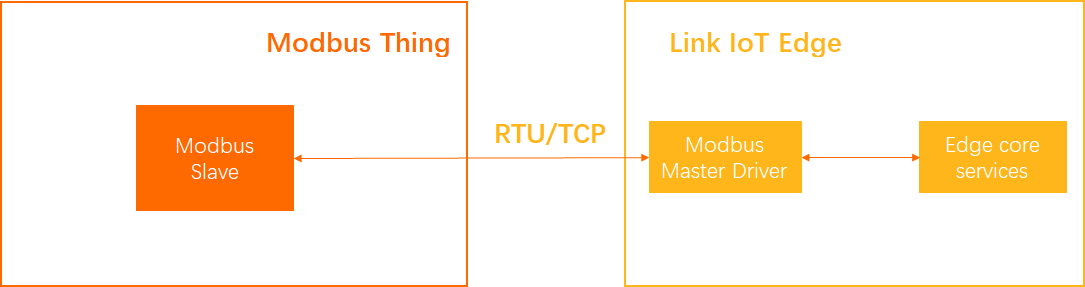
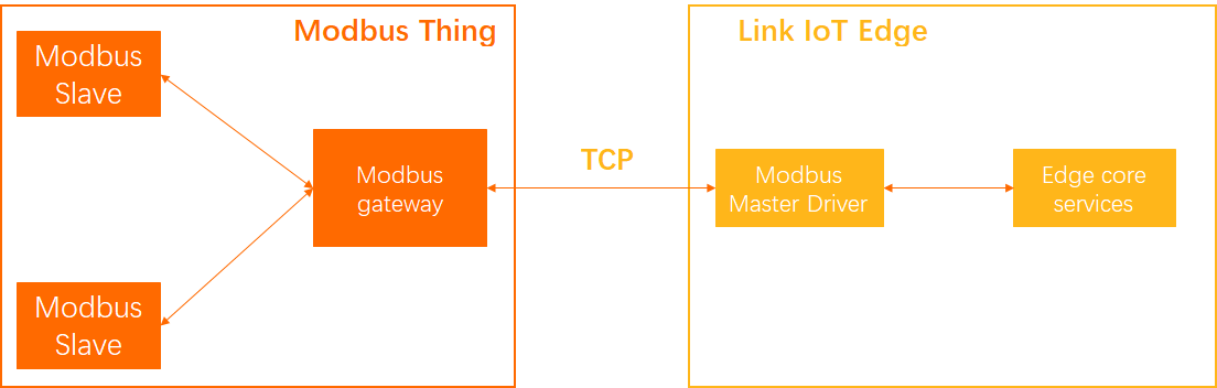
The Modbus driver can read input status and input registers. It can also read and write coil status and holding registers.
Link IoT Edge provides Modbus drivers for C and Python. Multiple C language Modbus drivers are available to support different CPU architectures. You can deploy a Modbus driver to a gateway directly from the console. You can also download the Modbus driver source code from the console, modify it, and then use it as a custom driver.
This topic describes how to use the official Modbus driver.
Prerequisites
Before you begin, make sure that you have created an edge instance and that the gateway is online. For more information, see Set up the environment.
Step 1. Assign the driver
- Log on to the IoT Edge console.
- In the navigation pane on the left, click Edge Instances. Find the edge instance that you created and click View in the Actions column.
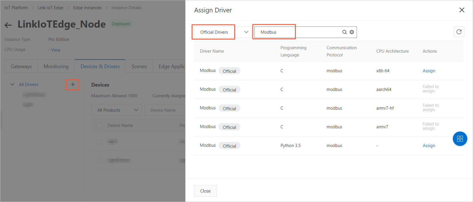
- On the Instance Details page, click the Devices & Drivers tab. Then, click the
+icon next to All Drivers. - In the Assign Driver panel, select Official Driver. Find the Modbus driver that matches your gateway's CPU architecture and click Assign in the Actions column. Then, click Close.Note
- The C language Modbus driver requires Link IoT Edge v1.8.4 or later.
- The Python language Modbus driver is supported only in Link IoT Edge Pro Edition.
Step 2. Configure the driver
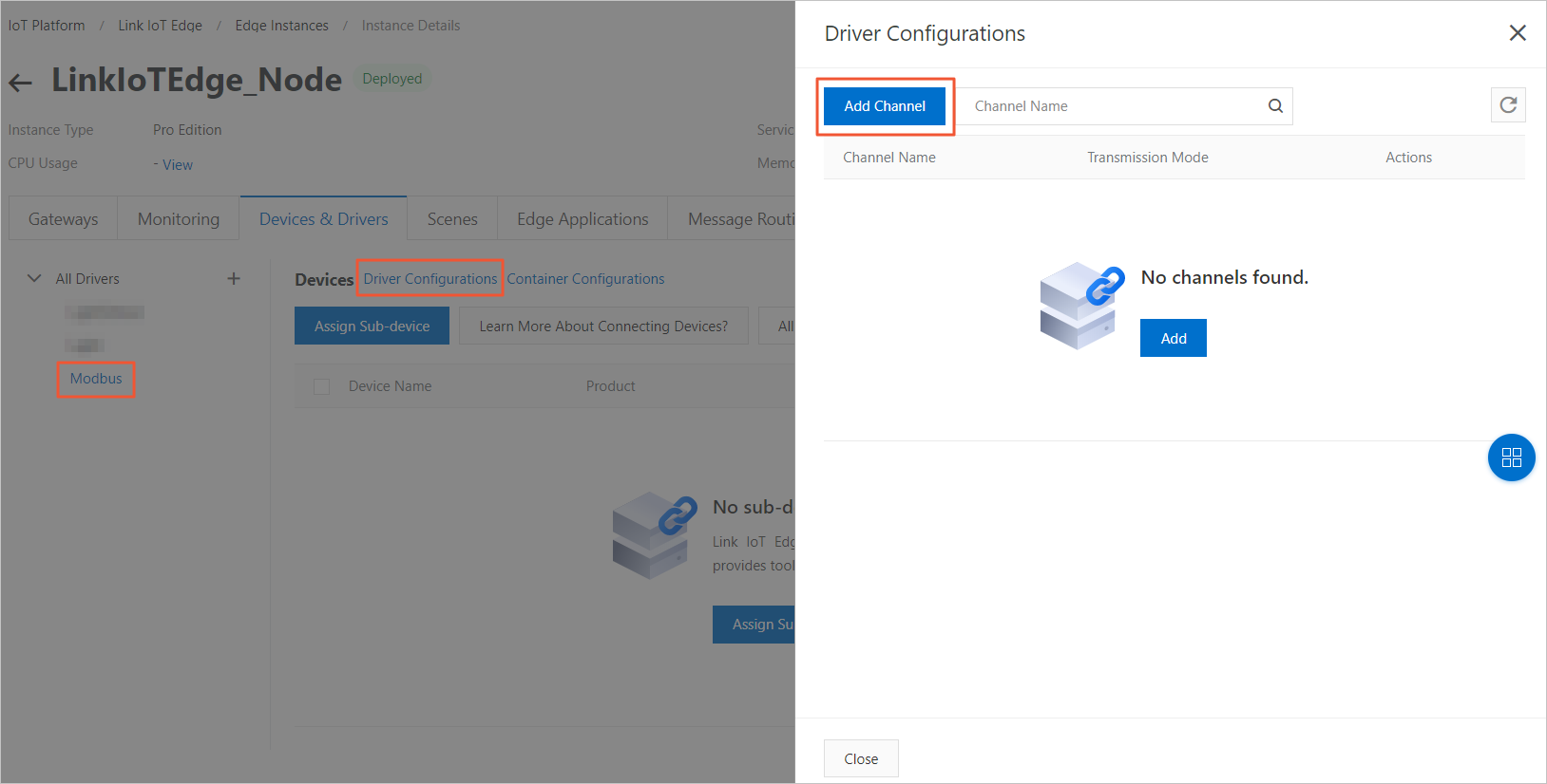
- Click the Modbus driver that you assigned. In the Device List section, click Driver Configuration.
- In the panel that appears, click Add Channel.A channel is the connection medium between the gateway and a physical device.
- Set the parameters as described in the following table and click OK.
Parameter Description Channel Name A unique name for the channel within the gateway. The name can be 1 to 30 characters long and can contain Chinese characters, letters, digits, and underscores (_). A Chinese character is counted as two characters. Transmission Mode Supported modes are RTU, TCP, and LoRa LAN.
If you set Transmission Mode to RTU, set the following parameters: Serial Port The serial port, such as /dev/ttyUSB0 or /dev/ttyUSB1. The port name can be 1 to 64 characters long and can contain letters, digits, forward slashes (/), and underscores (_). Baud Rate The number of symbols transmitted per second. Select a value from the drop-down list. Data Bit The number of data bits in a data group. Select a value from the drop-down list. Parity Bit Select odd parity, even parity, or no parity from the drop-down list. Stop Bit The last bit of a single packet. Select a value from the drop-down list. If you set Transmission Mode to TCP, set the following parameters: IP Address The IP address of the Modbus device. Enter the address in dotted decimal notation. Port Number The port number of the Modbus device. Enter an integer from 1 to 65535. If you set Transmission Mode to LoRa LAN, set the following parameters: DevAddrThe device address. Enter an 8-digit hexadecimal value, such as66be****.AppSKeyThe application session key. Enter a 32-digit hexadecimal value, such as623bd505f042090b5af660954509****.NwkSKeyThe network session key. Enter a 32-digit hexadecimal value, such ase1336a94a03aa3beae55b737acda****.ClassThe class of the communication node. Currently, only C is supported. This means the device can receive data at any time. Uplink FPortThe uplink application port. The value must be in the range of 1 to 223.Downlink FPortThe downlink application port. The value must be in the range of 1 to 223. - (Optional) Next to Driver Configuration, click Container Configuration to configure the container for the current driver. After you complete the configuration, click Save. Note Product specificationsContainer Configuration: You can set only for edge instances of the Professional Edition.
Parameter Description Use Host Network Specifies whether to isolate the container's network and use the host network environment directly. - Yes: The container's network is not isolated. The host network is used directly.
- No: The container's network is isolated. You must configure Port Mapping.
Port Mapping This parameter appears when Use Host Network is set to No. The network environment of the function is completely isolated from the host environment. Through port mapping, you can map the listening port of the function in the container to a port on the host. This allows client programs on different hosts to access the service provided by the function. You can map up to 10 network ports. For example, the
fc-http-serverfunction runs in a container on the host and provides services on port 80. In this case, client programs on other hosts cannot access thefc-http-serverfunction by accessing port 80 of the host. Therefore, you need to map the container port of thefc-http-serverfunction to a port on the host. For example, map port 80 in the container to port 8080 on the host. This allows client programs on other hosts to access thefc-http-serverfunction in the container by accessingHost IP address:8080.Enable Privileged Mode The root user in a container is actually a regular user on the host. To perform operations that require root permissions inside the container, such as modifying the system time or using the mount command, you must grant the container privileged mode.
Note In privileged mode, the container has root permissions on the host. All host devices are mapped to the container by default. You do not need to configure Device Mapping.Device Mapping This parameter appears when Enable Privileged Mode is set to No. The device management system is completely isolated from the host environment. When a function needs to access a host device, such as a serial port, you must map the device to the container where the function runs. You can add up to 10 device mappings. Volume Mapping The file system is completely isolated from the host environment. When a function needs to access a host file, you must map the file to the container where the function runs. You can add up to 10 volume mappings. Memory Limit Set the maximum memory for the container. - If the container's memory usage exceeds the limit, the container is restarted.
- If the memory limit is too small, the application in the container may fail to run.
The default memory is 1024 MB. Increase the memory limit based on the size of the application in the container.
Step 3. Associate the driver with sub-devices
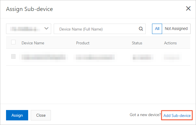
- In the Device List area, click Assign Sub-device to assign a sub-device to the Modbus driver.You can assign an existing Modbus device or create a new one.Note When you assign an existing Modbus device, the product to which the device belongs must be configured to connect to a gateway and use the Modbus protocol. For more information, see Create a product.
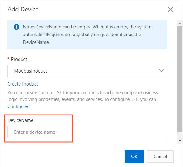
- In the Assign Sub-device panel, click Add Sub-device.
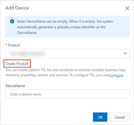
- In the Add Device dialog box, click Create Product to create a product for the Modbus device.

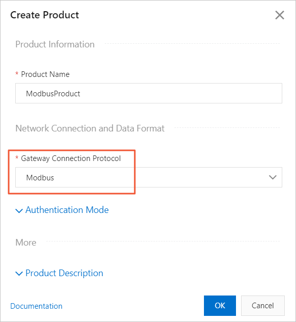
- In the Create Product dialog box, set the parameters and then click Done.
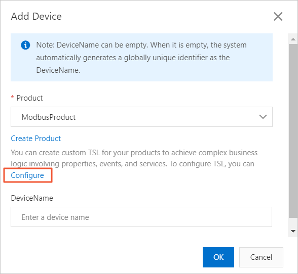
Table 1. Parameter description Parameter Description Product NameThe name of the product. The name must be unique within your account. It can contain Chinese characters, letters, digits, underscores (_), hyphens (-), at signs (@), and parentheses (()). The name must be 4 to 30 characters long. One Chinese character counts as two characters. CategorySelect a category to define a Thing Specification Language model for the product. Here, select Custom Category. Gateway ProtocolYou must select Modbus. Authentication MethodSelect an authentication method for your device. For more information, see Device security and authentication.Product Description Add a description for the product. This can be empty. - In the Add Device dialog box, the product that you created is automatically selected in the Product field. Click Configure for the product to add custom features.Note You can also use the Modbus debugging tool to configure the Modbus product. However, you must first add the device and assign it to the edge instance before using the debugging tool.
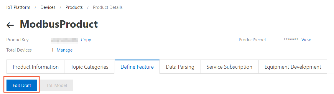
You are redirected to the Function Definition tab on the Product Details page in the IoT Platform console. Click Edit Draft. On the page that appears, click Add Custom Feature.
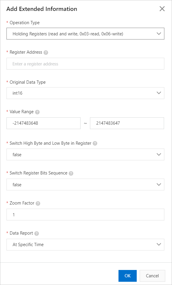
- In the Add Custom Feature dialog box, set the property parameters as required. For detailed instructions, see Add a TSL model individually.While you configure the TSL model properties, click Add Extended Description to set the Extended Description parameters. This step maps the properties to registers. The official Modbus driver aggregates all properties into Modbus data requests. After the driver receives the Modbus data, it converts the data into Thing Specification Language (TSL) model data.
The following parameters are available. For detailed explanations, see the "Extended description" section in Add a TSL model individually.
Name Description Operation Type The function code for the Modbus operation. Note- Coil Status: Function code 0x01 is always used for reading. For writing, you can use the single write function code 0x05 or the multiple write function code 0x0F.
- Holding Register: Function code 0x03 is always used for reading. For writing, you can use the single write function code 0x06 or the multiple write function code 0x10.
- If you select 0x06 for writing, you can only select int16 or uint16 for the Raw Data Type
- If you select 0x10 for writing, you can select any data type for the Raw Data Type parameter.
- Discrete Input: Function code 0x02 is always used for reading. Writing is not supported for this type.
- Input Register: Function code 0x04 is always used for reading. Writing is not supported for this type.
For more information about Modbus protocol specifications, see GB/T 19582.1-2008, GB/T 19582.2-2008, and GB/T 19582.3-2008.
Register Address Enter a hexadecimal value that starts with 0x.Set the register address based on the property address of your device. For example, to debug the temperature property, if your device's temperature property address is 1, you can set the register address to 0x1.
Raw Data Type For example, the data type of the collected temperature value is float. Value Range The value range refers to the range of the raw data after it is processed by the zoom factor. Data outside this range is discarded. Swap high and low bytes in register Specifies whether to swap the first 8 bits and the last 8 bits of the 16-bit data in the register. Here, set it to swap (true). Swap register order Specifies whether to swap the bits of the 32-bit raw data. Here, set it to not swap (false). Zoom Factor The scaling coefficient. For example, if the collected value is 100 but the actual value is 10, you need to scale it down by a factor of 10. In this case, set the zoom factor to 0.1. To scale it up by a factor of 10 (the actual value is 1000), set the zoom factor to 10. Data Reporting Method There are two data reporting methods. - Report on schedule: If you select Report on schedule, data is collected and reported based on the Data Collection Interval that you set for the sub-device in step 9.
- Report on change: Data is reported only when the collected value changes.
- Return to the Instance Details page to add the Modbus device.
- Assign the new Modbus device to the edge instance.
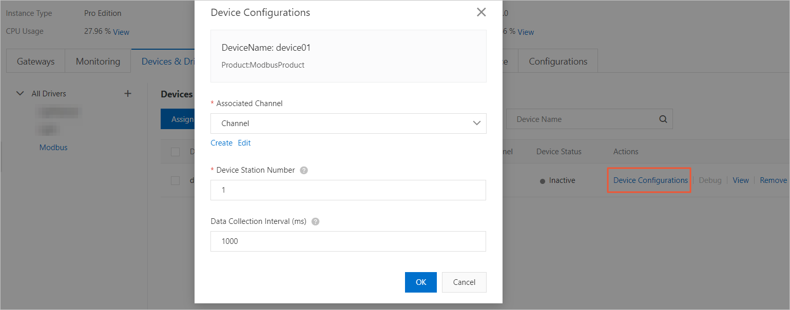
- After you assign the device to the edge instance, click Device Configuration in the Actions column of the device. In the panel that appears, associate the device with the Modbus driver by selecting a channel.
Table 2. Parameter description Parameter Description Associated Channel Select the channel created in step 2 of Configure the driver. Slave ID The slave ID is the identifier for the Modbus device. It must be unique within the same channel. Data Collection Interval The Modbus protocol is a half-duplex protocol. The gateway actively requests data. You must specify the interval for collecting data from data points. The unit is milliseconds. Note The time required to collect a single data point is about 60 milliseconds (ms). The collection interval is calculated as follows:
For example, if there are 10 devices on the current Modbus bus channel and each device has 10 data points, the collection interval must be greater than or equal to 6000 ms (60 ms × 10 × 10 = 6000 ms). This ensures that each data point can be reported normally.Collection time (60 ms) × Total number of data points for the channel
Step 4. Deploy the edge instance
- (Optional) Before you deploy the instance, you can use the Modbus debugging tool to test whether the gateway can connect to the Modbus device and whether the TSL model of the product is configured correctly.
- On the Instance Details page, click Deploy in the upper-right corner to deploy the edge instance.
FAQ
When the official Modbus driver reports messages to the cloud, does it report them by device or by property?
A: The official Modbus driver collects and reports data on a per-device basis during each collection period. For example, if a Modbus device has 100 properties and the data collection interval is 5 seconds, the Modbus driver reports one message to the cloud every 5 seconds because all properties belong to a single device.