The Maximum Connected Subgraph algorithm finds the largest connected component in an undirected graph — the largest set of nodes where any two nodes are reachable from each other via a path. It uses depth-first search (DFS) or breadth-first search (BFS) to traverse the graph, identify all connected components, and return the one with the most nodes. Typical use cases include network analysis and image processing.
This algorithm operates on undirected graphs. Edge direction is ignored during traversal.
Configure the component
Method 1: Configure the component on the pipeline page
On the pipeline page of Machine Learning Designer in the Platform for AI (PAI) console, configure the Maximum Connected Subgraph component using the parameters described in the following table.
| Tab | Parameter | Description |
|---|---|---|
| Fields Setting | Start Vertex | The start vertex column in the edge table. |
| End Node | The end vertex column in the edge table. | |
| Tuning | Workers | The number of worker nodes for parallel job execution. Higher values increase parallelism but also increase framework communication overhead. |
| Memory Size per Worker (MB) | The maximum memory per worker, in MB. Default: 4096. If a worker exceeds this limit, an OutOfMemory error is reported. |
|
| Data Split Size (MB) | The size of each data split, in MB. Default: 64. |
Method 2: Use PAI commands
Configure the Maximum Connected Subgraph component by running PAI commands in the SQL Script component. For more information, see Scenario 4: Execute PAI commands within the SQL script component.
PAI -name MaximalConnectedComponent
    -project algo_public
    -DinputEdgeTableName=MaximalConnectedComponent_func_test_edge
    -DfromVertexCol=flow_out_id
    -DtoVertexCol=flow_in_id
    -DoutputTableName=MaximalConnectedComponent_func_test_result;
The following table describes the PAI command parameters.
| Parameter | Type | Required | Default | Description |
|---|---|---|---|---|
inputEdgeTableName |
String | Yes | — | The name of the input edge table. |
inputEdgeTablePartitions |
String | No | Full table | The partitions to read from the input edge table. |
fromVertexCol |
String | Yes | — | The start vertex column in the input edge table. |
toVertexCol |
String | Yes | — | The end vertex column in the input edge table. |
outputTableName |
String | Yes | — | The name of the output table. |
outputTablePartitions |
String | No | — | The partitions to write in the output table. |
lifecycle |
Integer | No | — | The lifecycle of the output table. |
workerNum |
Integer | No | — | The number of worker nodes for parallel job execution. |
workerMem |
Integer | No | 4096 | The maximum memory per worker, in MB. If a worker exceeds this limit, an OutOfMemory error is reported. |
splitSize |
Integer | No | 64 | The size of each data split, in MB. |
Example
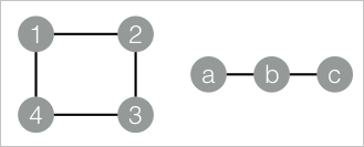
This example creates an edge table with two connected components — nodes {1, 2, 3, 4} and nodes {a, b, c} — then runs the algorithm to identify which component each node belongs to.
-
Add a SQL Script component to the canvas and run the following SQL statements to create the input edge table.
drop table if exists MaximalConnectedComponent_func_test_edge;
create table MaximalConnectedComponent_func_test_edge as
select * from
(
  select '1' as flow_out_id,'2' as flow_in_id
  union all
  select '2' as flow_out_id,'3' as flow_in_id
  union all
  select '3' as flow_out_id,'4' as flow_in_id
  union all
  select '1' as flow_out_id,'4' as flow_in_id
  union all
  select 'a' as flow_out_id,'b' as flow_in_id
  union all
  select 'b' as flow_out_id,'c' as flow_in_id
)tmp;
drop table if exists MaximalConnectedComponent_func_test_result;
create table MaximalConnectedComponent_func_test_result
(
  node string,
  grp_id string
);
The graph structure is as follows:
-
Add another SQL Script component to the canvas and run the following PAI commands to execute the algorithm.
drop table if exists ${o1}; PAI -name MaximalConnectedComponent -project algo_public -DinputEdgeTableName=MaximalConnectedComponent_func_test_edge -DfromVertexCol=flow_out_id -DtoVertexCol=flow_in_id -DoutputTableName=${o1}; -
Right-click the SQL Script component and choose View Data > SQL Script Output to view the results. The output has two columns:
nodeis each node in the graph, andgrp_idis the ID of a representative node in its connected component. All nodes sharing the samegrp_idbelong to the same connected component. In this example, nodes a, b, and c form one component (representative: c), and nodes 1, 2, 3, and 4 form the other (representative: 4).node grp_id a c b c c c 1 4 2 4 3 4 4 4