Implement active zone-redundancy using an MSE cloud-native gateway
Cloud-native gateways are deployed across multiple zones by default. This provides global traffic management at the region level and across zones. In an active zone-redundancy scenario, this ensures efficient load balancing for requests to multiple service clusters across different zones. If a service cluster in a single zone fails, the failed node is automatically removed within one second to implement failover. This ensures service continuity and high availability.
Disaster recovery overview
Cloud disaster recovery is classified into the following three main types:
Same-City Cross-AZ Disaster Recovery
Zone-disaster recovery includes active-active and active-standby disaster recovery. Data centers in the same city are physically close, which results in low network latency. This helps prevent zone-level disasters, such as fires, network disconnections, or power outages.
Cross-region active-active disaster recovery
Cross-region active-active disaster recovery has relatively high network latency. However, it can prevent regional disasters, such as earthquakes and floods.
Two-region three-data-center architecture
The two-region three-data-center architecture combines dual data centers in the same city with cross-region disaster recovery. This architecture combines the advantages of both methods and is suitable for scenarios that require high application continuity, data continuity, and availability.
In practice, zone-disaster recovery is easier to implement for data than cross-region disaster recovery. Therefore, zone-disaster recovery remains an important strategy.
Features and benefits
A disaster recovery plan that uses a cloud-native gateway has the following advantages over a plan that uses the Domain Name System (DNS) for traffic distribution:
Cloud-native gateways are deployed across multiple zones by default and provide global traffic management at the region level.
A disaster recovery plan that uses DNS for traffic distribution requires you to manually adjust the traffic ratio for each cluster. In contrast, a plan that uses a cloud-native gateway dynamically adjusts the traffic ratio for each cluster based on the total number of workloads. For scenarios where peer deployment cannot be guaranteed, this helps prevent backend services from crashing in clusters with fewer deployed resources.
Disaster recovery that uses a multi-cluster gateway supports Layer 7 routing and forwarding, whereas disaster recovery that uses DNS for traffic distribution does not.
In a disaster recovery plan that uses DNS for traffic distribution, client-side caching during an IP address switchover often causes temporary service unavailability. In contrast, a plan that uses a cloud-native gateway can smoothly fail over traffic to the backend service of another cluster.
Architecture
With the global traffic management capability of a cloud-native gateway across zones in the same region, if a single zone (Zone I) fails, 100% of the traffic is automatically routed to another zone (Zone J).
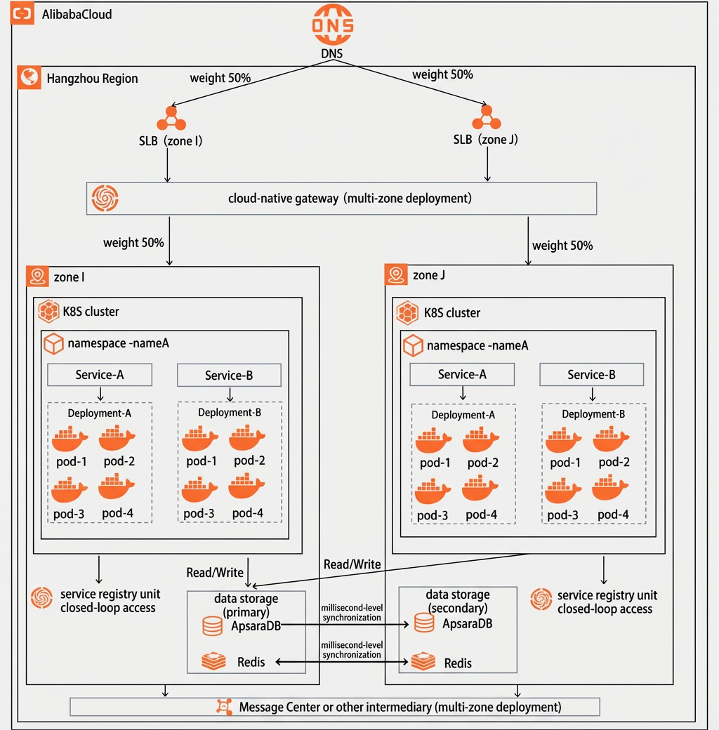
One Server Load Balancer (SLB) instance in each of the two zones helps prevent a single point of failure (SPOF) for the SLB instances. If an SLB instance in a single zone fails, you can switch traffic using DNS.
A single cloud-native gateway is deployed across multiple zones to provide global traffic management for multiple service clusters across zones. This ensures load balancing for requests to multiple clusters and enables automatic traffic switching within seconds after a single zone fails.
Each cluster corresponds to a Nacos instance. This ensures that microservice invocations form a closed loop within a zone. If a single zone fails, the gateway automatically switches traffic to ensure that no microservice invocation traffic is lost.
Preparations
Create a Kubernetes (K8s) cluster in each of two different zones. For more information, see Create an ACK managed cluster.
Create a self-managed K8s cluster using kubeadm.

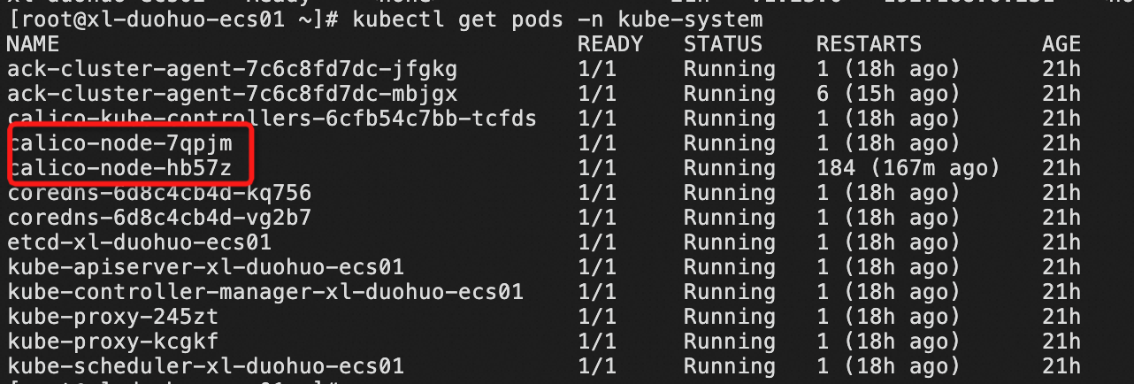
Check the cluster network mode. The cluster uses the Calico network plug-in, and the network mode is Calico IPIP.
Connect the self-managed cluster as a registered cluster. For more information, see Connect a target cluster to a registered cluster.
The self-managed K8s cluster uses the Calico IPIP network mode, which requires traffic from cloud resources to pods to be forwarded through a node. After you connect the cluster, you must add a route entry to the VPC route table that maps the pod CIDR block to the node.
NoteEstablish network connectivity as needed. For more information, see Hybrid cloud networking overview.
Create a cloud-native gateway.
NoteWhen you create the cloud-native gateway, select multi-zone deployment. Make sure that the new cloud-native gateway and your clusters are in the same VPC.
If a Kubernetes (K8s) cluster that you use for active zone-redundancy is a self-managed cluster in an IDC or on another cloud platform, you can connect the on-premises cluster to the cloud by following the ACK One Quick Start for registered clusters. In this topic, the K8s cluster in Zone I is a self-managed cluster that is connected to the cloud as a registered cluster.
Video tutorial
Step 1: Deploy the demo application in the clusters
Log on to the Container Service for Kubernetes (ACK) console. Use the following YAML files to deploy the demo application in the ACK clusters that are in different zones. Replace the values of
nacos_addressandenvwith your actual environment parameters.After the deployment is successful, two workloads and one service appear in the corresponding ACK cluster.
Step 2: Create sources
Create two service sources in the cloud-native gateway and associate them with the container clusters in the two zones. For more information, see Create a service source.
Step 3: Create a service
Create a service in the cloud-native gateway. For more information, see Add a service.
The cloud-native gateway supports unified management of services across clusters. When you create a service, services that have the same name in the same namespace across the two K8s clusters are automatically merged.
Step 4: Create a routing rule in the cloud-native gateway
Create a routing rule in the cloud-native gateway and set the domain name and matching rule. Select the destination service, and then save and publish the routing rule. For more information, see Create a routing rule.
Step 5: Verify the traffic switching effect
The cloud-native gateway can dynamically adjust traffic based on the number and health status of workloads in the backend clusters. This topic demonstrates the automatic traffic switching effect of the cloud-native gateway in scenarios with peer deployment, non-peer deployment, and data center failure.
Use the following shell script to send requests to the gateway in a loop.
#!/bin/bash
for (( i = 1; i < 1000000000; i++ )); do
      curl http://114.55.XXX.XXX/helloActiveRedundancy  # Replace the IP address with the public IP address of your gateway.
      sleep 1
      echo
done
Peer deployment with an equal number of workloads in two clusters
The number of replicas for the workloads is the same in both clusters.
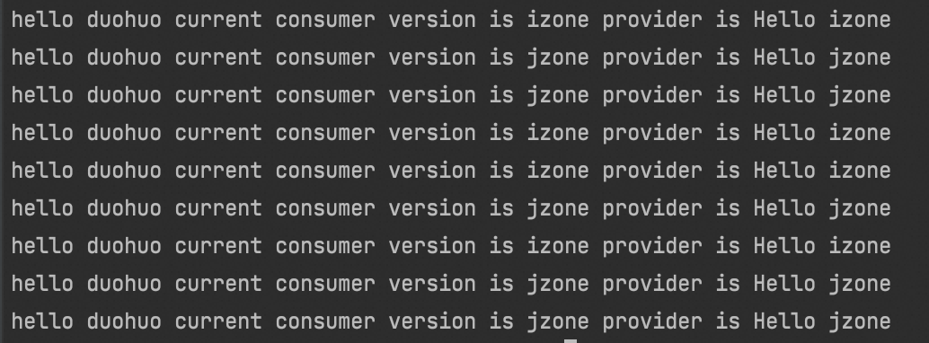
Run the shell script to send requests. The output shows that the traffic is load-balanced between Zone I and Zone J. Each cluster handles 50% of the traffic.
Non-peer deployment with an unequal number of workloads in two clusters
Scale in the number of replicas in the cluster in Zone I to 1.
Run the shell script to send requests. The output shows that the cluster in Zone J handles 90% of the traffic and the cluster in Zone I handles 10% of the traffic.

Automatic traffic switching in a data center failure scenario
Scale in the number of replicas in the cluster in Zone I to 0. Run the shell script to send requests. The output shows that 100% of the traffic is automatically switched to Zone J.

Performance Testing Service (PTS) stress testing
Use PTS to run a stress test to further observe the timeliness of automatic traffic switching and the traffic loss during the process after a failure in Zone I.
Create a stress testing scenario in PTS:
Set the records per second (RPS) for the stress test to 100, and then click Save and Run Test.
After the stress test runs for one minute, manually delete all workloads in the cluster in Zone I to simulate a cluster failure. Then, monitor the traffic loss.
The result shows that after the cluster in Zone I fails, Microservices Engine (MSE) switches traffic within seconds. Less than 1% of the traffic is lost during the switching process.