Configure block interfaces
This topic describes how to configure and use block interfaces in the Scenario Editor.
Procedure
On the Scenario Editor page, you can click the
 icon in the upper-right corner of the toolbar. In the Data Interface Settings dialog box, you can configure the data interface details. For more information, see Data interface configuration.
You can click the
 icon in the upper-right corner of the toolbar. In the Event Settings dialog box, you can configure the event interface details. For more information, see Event interface configuration.
You can click the
 icon in the upper-right corner of the toolbar. In the Action Settings dialog box, you can configure the action interface details. For more information, see Action interface configuration.
After you configure the interface content, you can click the
 icon in the upper-left corner of the Scenario Editor page to open the Blueprint Editor.
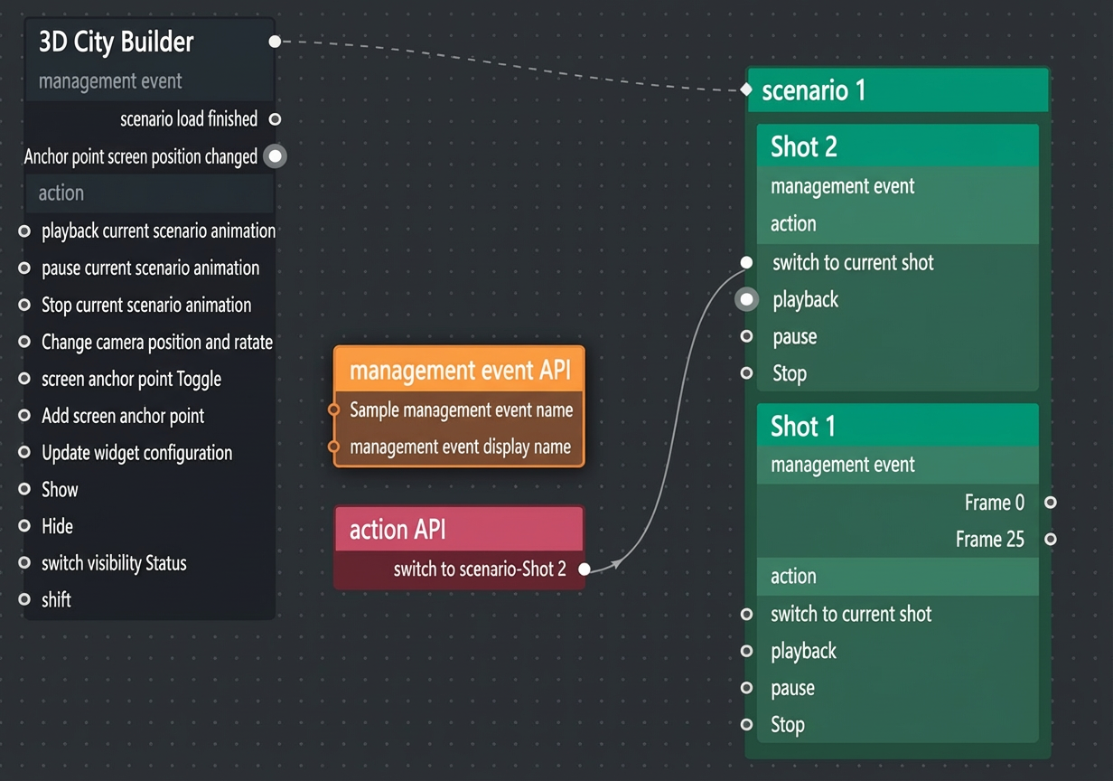
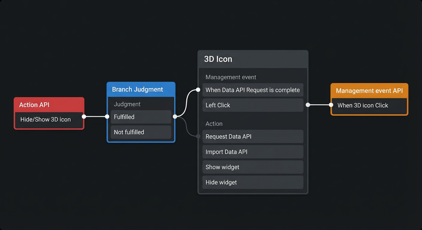
In the Logic Node panel, you can click Block Interface to configure the blueprint for the interactive interface node. For more information about the interface blueprint configuration, see Use block interfaces.
After you configure the block interface blueprint, you can click the
 icon in the upper-right corner of the page to open the 3D scene preview page. On the left side of the page, you can click Test Block Interface to open the Test Block Interface panel.
In the Test Block Interface panel, you can view the overall style of the block interface configured in the 3D scene. You can test the availability of each configuration using the content on the Data, Event, and Action tabs on the left side of the preview page. This topic uses the effect of a 3D Icon layer configured in the blueprint editor as an example.
Test
Operation
Test data
On the Data tab, enter different data, and check whether the data configuration of the internal layer works as expected. On the Data tab on the left, enter additional data and click the Test button below to view the changes in the data displayed in the 3D Icon layer.
Example of input data Example of test results after you delete data
Test event
On the Event tab, click an event in the block interface to check whether the data thrown by the interface is correct. Click an icon in the 3D Icon layer. In the Event Response Result section of the When 3D Icon is Clicked event tab on the left, listen for the data thrown when the icon is clicked.
Test action
On the Action tab, enter different parameters for an action to check whether the behavior of the corresponding internal widget works as expected. On the Action tab on the left, enter the hide parameter in the Test Parameter input box under Hide/Show 3D Icon to hide all icons in the 3D Icon layer.
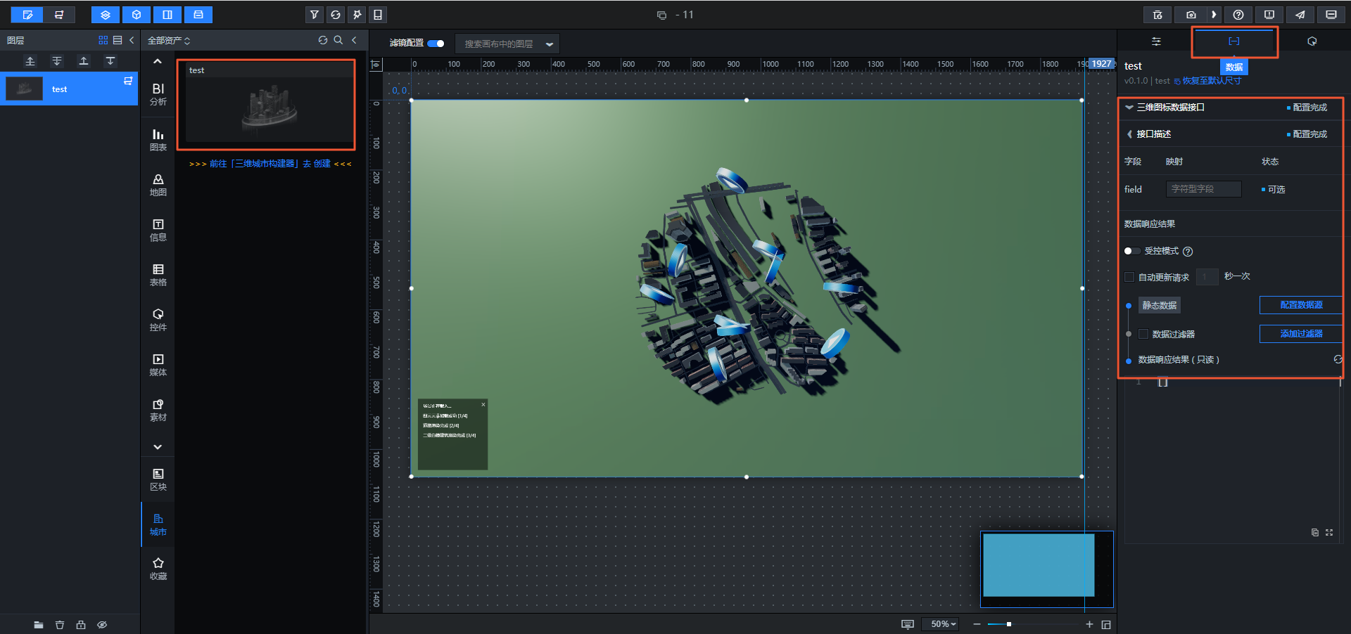
You can add the configured 3D city builder project to the canvas editor. For more information, see Preview, publish, and use projects. You can then view the custom data interface content and event settings that you configured for the project in the Data and Interaction panels on the right side of the canvas editor.
Data Interface Content panel
Event Settings Interaction panel
You can export the 3D city builder project to the blueprint editor. In the canvas editor, you can click the
icon in the upper-left corner to open the blueprint editor page. On the blueprint editor page, you can click the Import 3D City Builder Project node to view the custom action settings.
 icon in the upper-right corner of the page to open the 3D scene preview page. On the left side of the page, you can click Test Block Interface to open the Test Block Interface panel.
 icon in the upper-left corner to open the blueprint editor page. On the blueprint editor page, you can click the Import 3D City Builder Project node to view the custom action settings.