Toolbar
This document describes the features of the scene editor toolbar, such as switching editors, managing scenarios, and configuring block interfaces.
Preparations
Prerequisites
You have created a 3D city project.
Enter the scene editor
To use the toolbar, open the scene editor:
Access the DataV console.
On the Workbench page, in the All Applications section, hover over the target 3D city project and click Edit to open the scene editor.
Basic operations
Switch editors
On the Scene Editor page, click the
 icon in the upper-left corner to open the Blueprint Editor.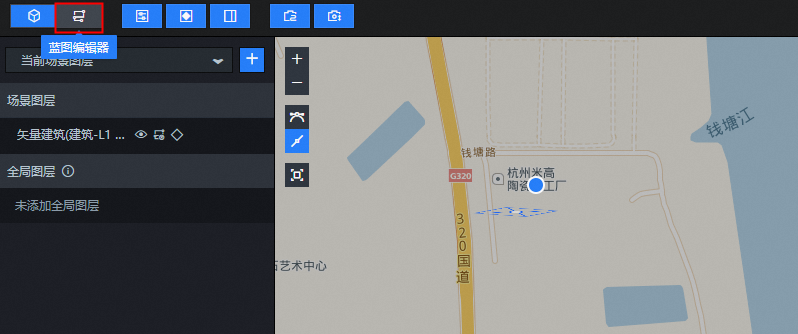
On the Blueprint Editor page, click the
 icon in the upper-left corner to switch back to the scene editor.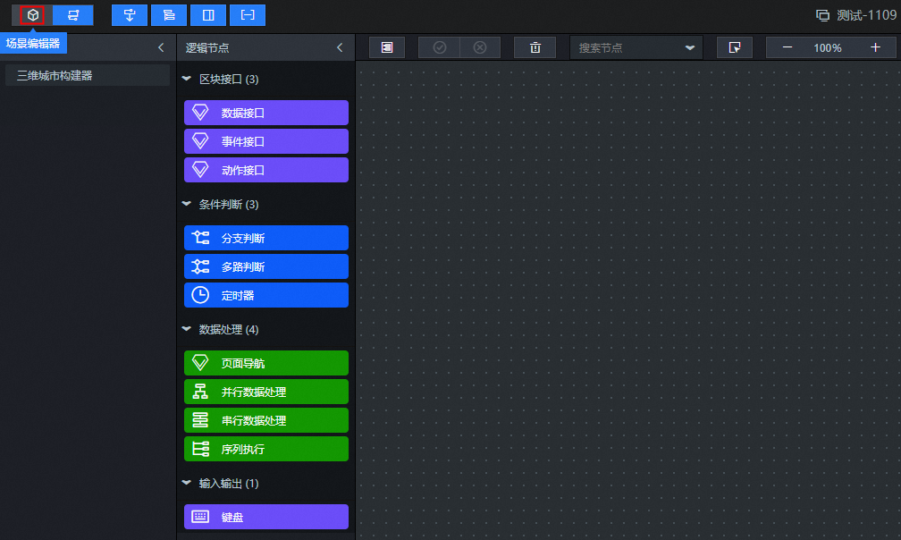
Show or hide panels
On the Scene Editor page, hover over the five panel toggle icons in the upper-left corner.
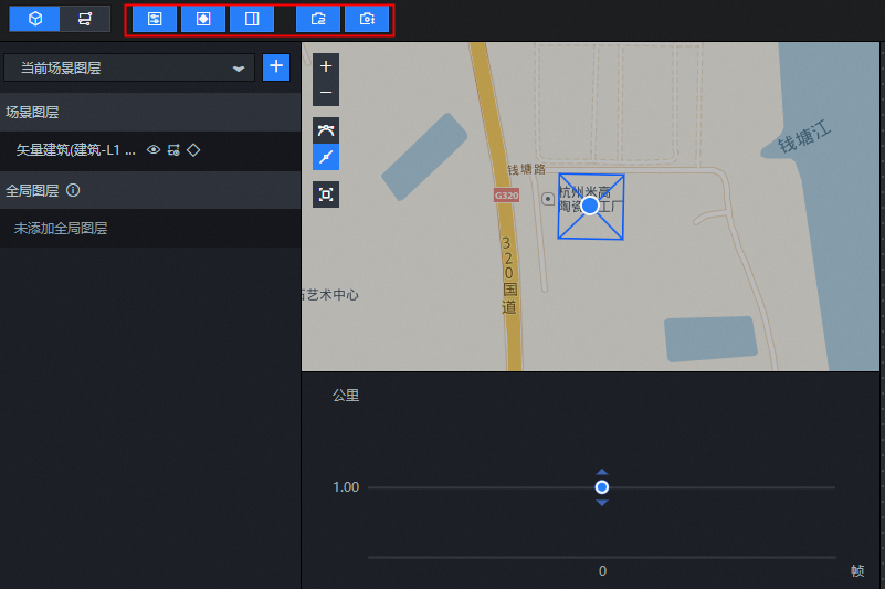
Click the
 icon to hide the layer panel on the left side of the scene editor.
Click the
icon to hide the keyframe panel at the bottom of the scene editor.Click the
icon to hide the scenario or layer configuration panel on the right side of the scene editor.Click the
icon to hide the camera path panel in the center of the scene editor.Click the
icon to hide the camera elevation panel in the center of the scene editor.
To show a hidden panel, click its grayed-out icon.
 icon to hide the layer panel on the left side of the scene editor.
 icon to hide the keyframe panel at the bottom of the scene editor.
 icon to hide the scenario or layer configuration panel on the right side of the scene editor.
 icon to hide the camera path panel in the center of the scene editor.
 icon to hide the camera elevation panel in the center of the scene editor.
Project settings
In the scene editor, click the  icon in the upper-right corner of the toolbar to open the Project Settings dialog box and configure the parameters.
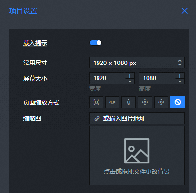
Parameter |
Description |
Loading Prompt |
Displays the loading status of the scenario on the published page. |
Common Sizes |
Sets the common dimensions for the project. Options include 1920 x 1080 px, 1440 x 810 px, 1280 x 720 px, 1024 x 768 px, and Custom Size. |
Screen Size |
Sets the screen resolution. You can use the Common Sizes setting for a one-click setup or manually adjust the width and height values. The default size is 1920 × 1080 px. |
Page Scaling Mode |
Select a suitable page scaling mode based on the project's screen size. Options include Full Screen, Scale to Fit Width, Scale to Fit Height, Scale to Fit Height (Scrollable), Scale to Fit and Center, and No Scaling. |
Thumbnail |
Click or drag a file into the thumbnail box to use a custom image as the project's thumbnail. You can also enter an image URL in the thumbnail address input box to upload an image from the web. |
Preview, publish, and use
Preview a 3D city
On the Scene Editor page, click the  icon in the upper-right corner of the toolbar to preview the 3D city.

Publish a 3D city
On the Scene Editor page, click the
icon in the upper-right corner of the toolbar.In the Publish Project dialog box, enter a note for the release in the Release Notes field and click Publish.
NoteAfter you publish the project, the 3D city is available on the City tab of the Widget Library in the canvas editor. You can also continue to modify the 3D city. For more information, see Scene editor.
 icon in the upper-right corner of the toolbar.
Use a 3D city
Log on to the DataV console.
On the Workbench page, select a data dashboard and click Edit to open the Canvas Editor.
In the navigation pane on the left, click . Click a 3D city to add it to the Canvas Editor for further editing.
Scenario management
In the scene editor of the 3D city builder, you can view all existing scenarios. By default, the system adds the initial layers to Scenario 1. You can perform operations such as adding and switching scenarios.
Create a scenario
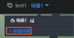
Click the scenario drop-down arrow at the top of the Scene Editor. In the scenario list, click New Scenario.
In the New Scenario dialog box, enter a name for the new scenario and click OK.
NoteA new empty scenario inherits the camera view of the current scenario but does not automatically include any layers. You can add new layers or assign layers from an existing scenario to the new one. For more information, see Layer panel.
Basic management operations
Click the scenario drop-down menu at the top of the Scene Editor to perform the following operations:
Switch scenario: Select a scenario from the list to switch to it.
Set default scenario: In the scenario list, click the
icon next to a scenario to set it as the default for project previews and publishing.Copy scenario: In the scenario list, click the
icon next to a scenario to copy it. The copy appears at the bottom of the list, and the editor automatically switches to it.Rename scenario: In the scenario list, click the
icon next to a scenario. In the Rename dialog box, enter a new name and click OK.Delete scenario: In the scenario list, click the
icon next to a scenario. In the Delete dialog box, click OK to delete the scenario.ImportantDeleting a scenario does not delete its layers. This operation cannot be undone. Proceed with caution.
 icon next to a scenario to set it as the default for project previews and publishing.
 icon next to a scenario to copy it. The copy appears at the bottom of the list, and the editor automatically switches to it.
 icon next to a scenario. In the Rename dialog box, enter a new name and click OK.
 icon next to a scenario. In the Delete dialog box, click OK to delete the scenario.
Blueprint interaction
Click the scenario drop-down menu at the top of the Scene Editor. In the scenario list, click the
icon next to a scenario to export it to the blueprint editor.NoteClick the
icon again to cancel the export. If you cancel the export, any node interactions that you configured in the blueprint editor will no longer work.On the Scene Editor page, click the
icon in the upper-left corner to switch to the Blueprint Editor.On the blueprint editor configuration page, drag the 3D City Builder node from the Imported Nodes pane on the left to the blueprint canvas. The scenario node that you exported to the blueprint editor automatically connects to the 3D City Builder node. The following figure shows the blueprint editor configuration parameters for a scenario node after a keyframe event is inserted.
Events
Parameter
Description
Frame x
Triggers an event when the scenario timeline reaches frame x. No data is returned.
Actions
Parameter
Description
Switch to This Shot
Switches to the current shot. No parameters are required.
Play
Plays the current shot animation. No parameters are required.
Pause
Pauses the current shot animation. No parameters are required.
Stop
Stops the current shot animation. No parameters are required.
 icon next to a scenario to export it to the blueprint editor.
Configure block interfaces
The toolbar provides features to configure data, event, and action interfaces. You can configure and use them as needed. For more information, see Configure and use interfaces.
Data interface configuration: Click the
icon on the toolbar in the upper-right corner of the Scene Editor page to open the Data Interface Settings dialog box. In this dialog box, you can configure the data interface.Event interface configuration: Click the
icon on the toolbar in the upper-right corner of the Scene Editor page to open the Event Settings dialog box. In this dialog box, you can configure the event interface.Action interface configuration: Click the
icon on the toolbar in the upper-right corner of the Scene Editor page to open the Action Settings dialog box. In this dialog box, you can configure the action interface.
 icon on the toolbar in the upper-right corner of the Scene Editor page to open the Data Interface Settings dialog box. In this dialog box, you can
  icon on the toolbar in the upper-right corner of the Scene Editor page to open the Event Settings dialog box. In this dialog box, you can
  icon on the toolbar in the upper-right corner of the Scene Editor page to open the Action Settings dialog box. In this dialog box, you can